
Electromagnetic marking device and methods for its use

a marking device and electromagnetic technology, applied in the field of electromagnetic marking devices, can solve the problems of limited options, difficult to learn, and not widely known, and achieve the effect of reducing the difficulty of visually impaired persons in labeling objects and essential objects

Active Publication Date: 2019-03-28
BLIND INSITES LLC
View PDF3 Cites 2 Cited by
  • Summary
  • Abstract
  • Description
  • Claims
  • Application Information

AI Technical Summary

Benefits of technology

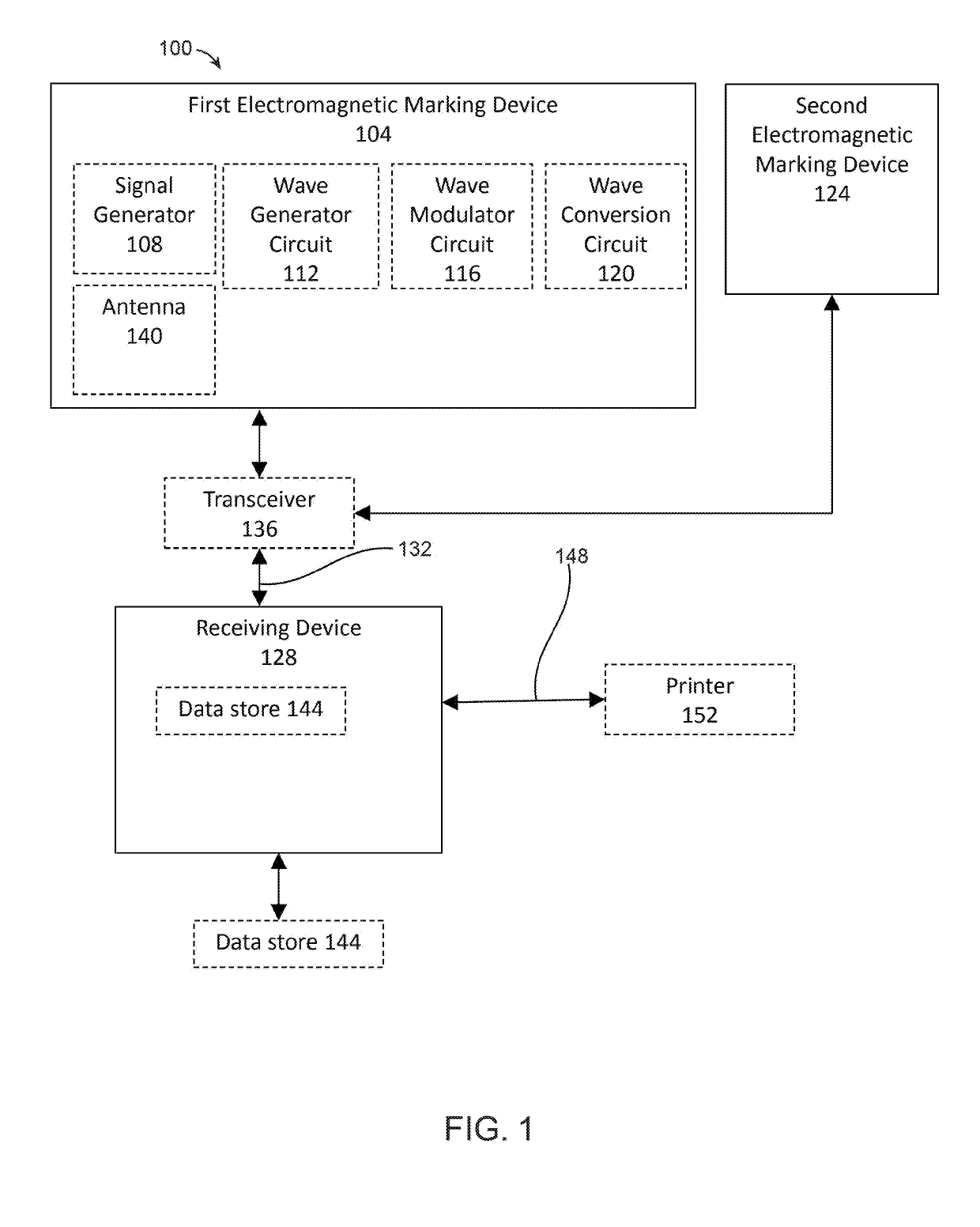
The patent describes a system for marking objects using an electromagnetic marking device. The device includes a body with a through-hole containing a first member. The first member has a first end attached to the body and a second end not attached to the body. The body also has a second part attached to the first part. The system also includes a signal generator attached to the second part. The signal generator has a wave generator circuit and a wave modulator circuit. This system can be used to mark objects with a unique electromagnetic signature for identification and tracking purposes.

Problems solved by technology

Labeling objects can be both difficult and essential for visually impaired persons.
It is difficult because there are limited options for labeling or marking an object in a way that is discernable non-visual means.
Braille works if a person knows how to read it, but is difficult to learn and not ubiquitously known.
Braille is also not easy to produce compared to writing with a pen, and produces labels that are hard to modify or swap to new objects.
The use of existing labeling in general is too inflexible and time-consuming for the purposes of replacing the ease with which visual identification can explain the contents of a container, closet, or room.

Method used


Image

  • Electromagnetic marking device and methods for its use
  • Electromagnetic marking device and methods for its use
  • Electromagnetic marking device and methods for its use

Examples


Embodiment Construction

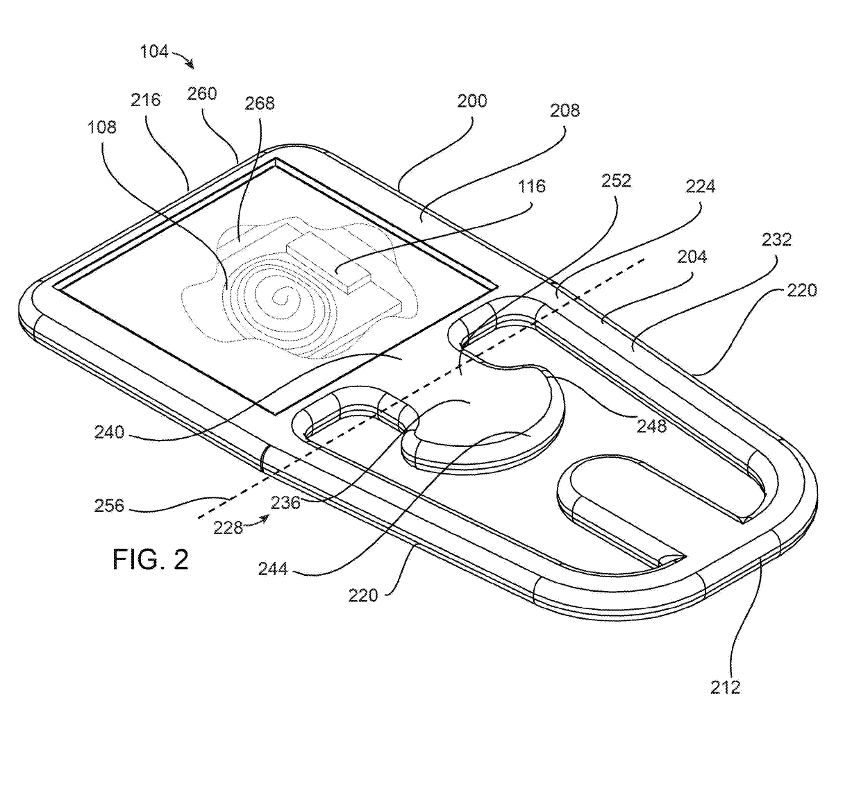
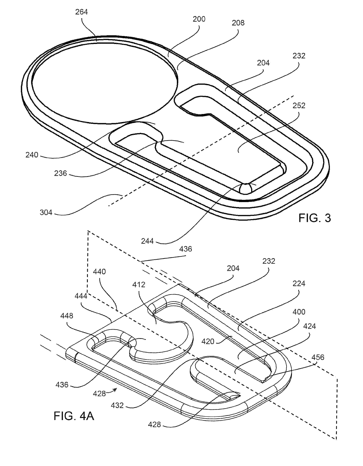
[0019]In an aspect, an electromagnetic marking device includes a first part with a signal generator and a second part that acts as a clip to attach the electromagnetic marking device to an object to be labeled. The signal generator, which may be writeable, transmits information to a computing device such as a mobile phone or tablet, either directly or via a separate transceiver; this may be accomplished using near-field communication among other things. The second portion may include a first member and / or a second member that may be inserted into openings or tabs, may grip an object against a base portion of the second portion, or may secure electromagnetic marking device to the object in various other ways. In operation, data is written to the signal generator, and the electromagnetic marking device is attached to an object; data may be metadata describing the object, which may be a document that has been printed.

[0020]Referring now to FIG. 1, an exemplary embodiment of a system 10...


PUM


Abstract

A system for marking objects using an electromagnetic marking device includes a first electromagnetic marking device, including a body having a top surface and a bottom surface. The body includes a first part having a through-hole in the first part, the through-hole having a first opening in the top surface of the body and a second opening in the bottom surface of the body, and a first member disposed within the through-hole, the first member including a first proximal end attached to the body and a first distal end not attached to the body. The body includes a second part attached to the first part. The electromagnetic marking, device includes a signal generator attached to the second part, the signal generator further including a wave generator circuit and a wave modulator circuit.

Description

RELATED APPLICATION DATA[0001]This application claims the benefit of priority of U.S. Provisional Patent Application Ser. No. 62 / 564,613, filed on Sep. 28 2017, and titled “ELECTROMAGNETIC MARKING DEVICE AND METHODS FOR ITS USE,” which is incorporated by reference herein in its entirety.FIELD OF THE INVENTION[0002]The present invention generally relates to the field of electronic communication devices. In particular, the present invention is directed to an electromagnetic marking device.BACKGROUND[0003]Labeling objects can be both difficult and essential for visually impaired persons. It is difficult because there are limited options for labeling or marking an object in a way that is discernable non-visual means. Braille works if a person knows how to read it, but is difficult to learn and not ubiquitously known. Braille is also not easy to produce compared to writing with a pen, and produces labels that are hard to modify or swap to new objects. The use of existing labeling in gene...

Claims


Application Information

Patent Timeline
Patent Type & Authority Applications(United States)
IPC IPC(8): G06K1/12
CPCG06K1/125
Inventor BELT, DARWIN WAYNE
Owner BLIND INSITES LLC
Learn More