Implantable bone adjustment devices

a bone adjustment device and implantable technology, applied in the field of implantable reconfigurable bone adjustment devices, can solve the problems of limited size of implanted devices in the medullary canal, prone to mechanical breakage, and limited device strength, and achieve the effect of reducing applied stresses

Active Publication Date: 2019-04-11
SMITH & NEPHEW INC
View PDF6 Cites 5 Cited by
  • Summary
  • Abstract
  • Description
  • Claims
  • Application Information

AI Technical Summary

Benefits of technology

[0015]In various embodiments, there is provided a reconfigurable bone adjustment device movable between a retracted state and an extended state. The bone adjustment device may include a first member configured for attachment to a first bone fragment; a second member configured for attachment to a second bone fragment, the second member including an elongated slot; a drive mechanism configured to move the second member relative to the first member; a threaded block fixedly coupled to the first member, the threaded block positioned within the elongated slot; a threaded rod having a proximal end operatively coupled to the drive mechanism, an intermediate portion threadably coupled to the threaded block, and a distal end operatively coupled to the second member so that rotation of the drive mechanism rotates the threaded rod and moves the second member relative to the first member; and means for reducing applied stresses at the junction between the threaded block and the first member.

Problems solved by technology

As can be appreciated, the size of these devices that are implanted in the medullary canal may be limited by the size of the medullary canal which may also limit the strength of these devices.
In such LLN devices, the first member or part and / or the second member or part are configured to carry some amount of limb load and therefore may be prone to mechanical breakage for various reasons.
This structure is referred to herein as a “driver.” In such LLN devices, it is a delicate balance between the appropriate amount of mechanical advantage using the drive mechanism, the appropriate amount of strength from the torsion of the magnet, and the appropriate amount of strength from the LLN device itself along with the size requirements of the LLN devices.
Often balancing all of these factors may lead to premature failure which results in the inability of the device to perform its intended bone adjustment action.
If the device is fully extended, then there is an increased possibility that the LLN device can fail under certain loading conditions.
Often the welded material is inherently weaker than the threaded block or the first member or part thereby causing a risk for failure at the weld junction if the implantable reconfigurable bone adjustment device is overloaded.
While currently available bone adjustment systems have produced excellent results, many of these devices exhibit one or more shortcomings or disadvantages that render the device susceptible to failure.
For example, a problem that has been encountered is that the stress concentrations at the point where the threaded block is affixed to the first member or part can cause failure of the device at this junction.
Failures of a device at this junction results in the inability of the device to perform its intended bone adjustment action.

Method used


Image

  • Implantable bone adjustment devices
  • Implantable bone adjustment devices
  • Implantable bone adjustment devices

Examples


Embodiment Construction

[0058]For the purposes of promoting an understanding of the principles of the present disclosure, reference will now be made to the embodiments illustrated in the figures and specific language will be used to describe the same. It will nevertheless be understood that no limitation of the scope of the present disclosure is thereby intended. Any alterations and further modifications in the described embodiments, and any further applications of the principles of the present disclosure as described herein are contemplated as would normally occur to one skilled in the art to which the present disclosure relates.

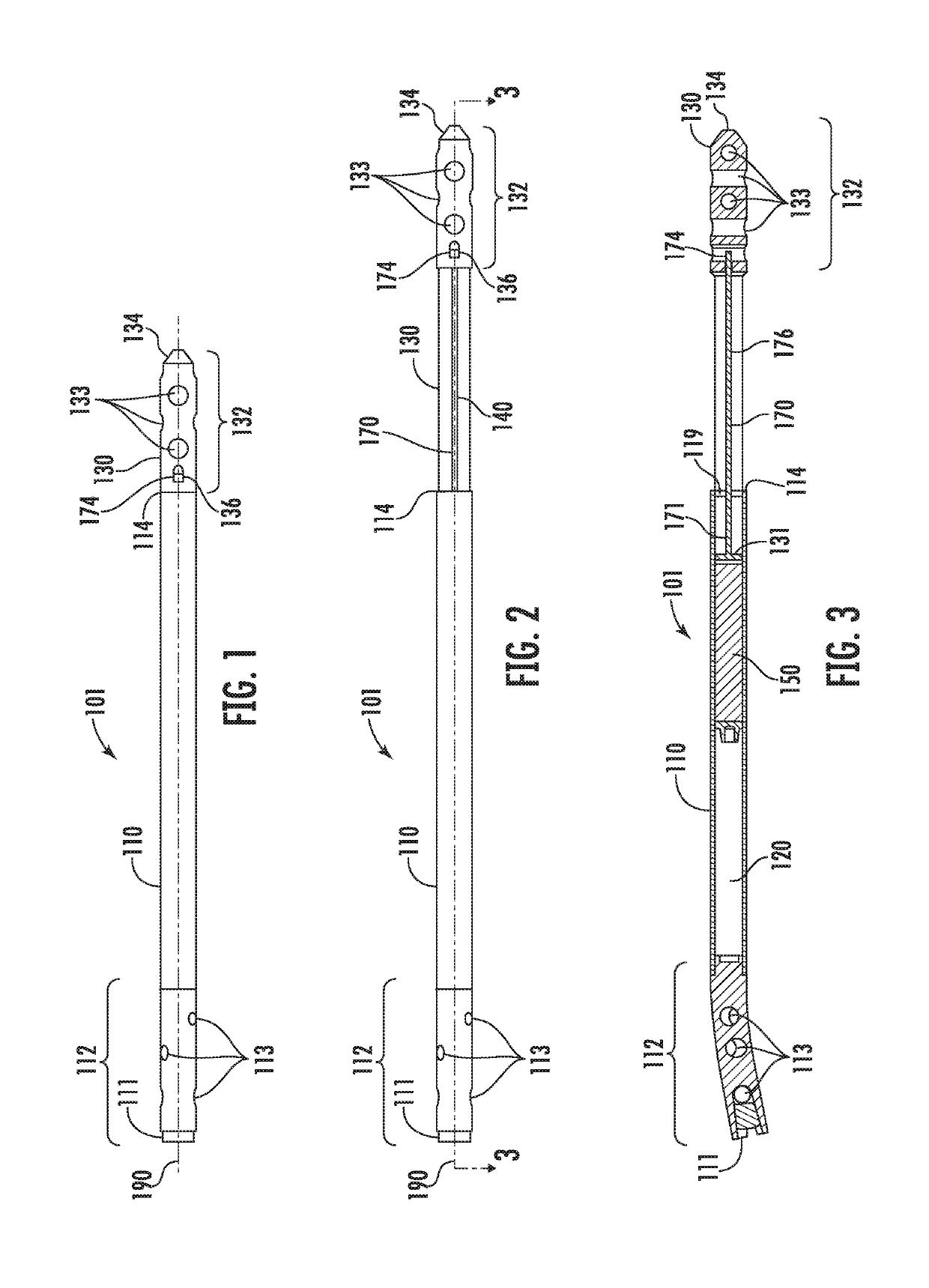
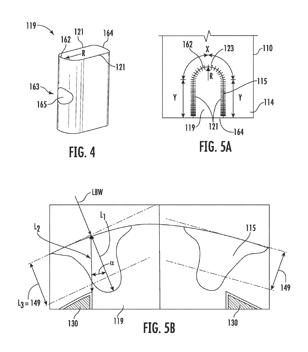
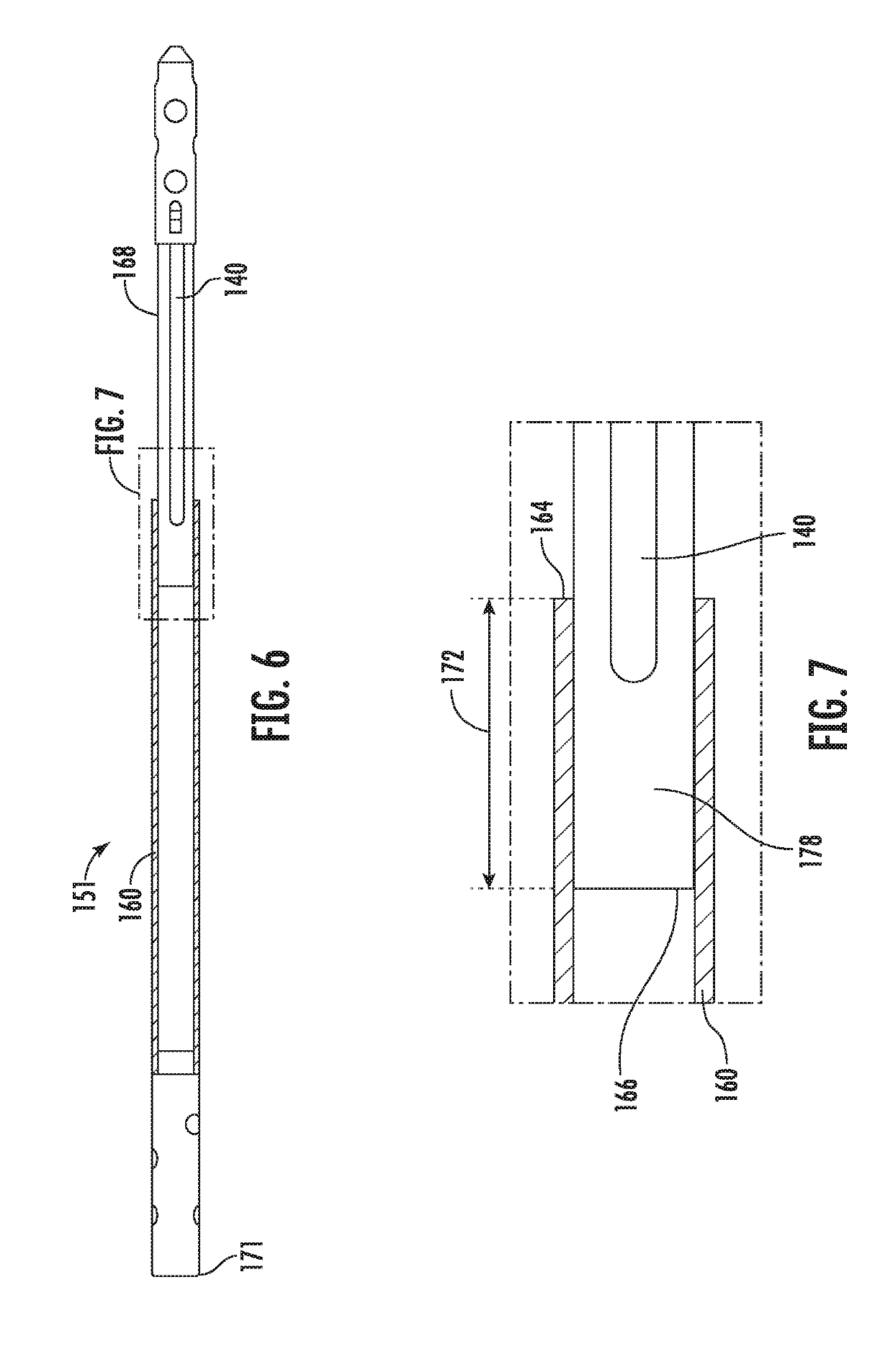
[0059]Various embodiments of implantable reconfigurable bone adjustment devices are disclosed herein. In some embodiments, the implantable reconfigurable bone adjustment devices may include a first member, part, body portion, or component (used interchangeably herein without the intent to limit), a second member, and a rotatable threaded rod that engages at least one component aff...


PUM


Abstract

A bone adjustment device such as, for example, an intramedullary lengthening nail may include a first or outer body portion having a notch, a second or inner body portion, a threaded shaft coupled to the first body portion to rotate relative thereto, an inner magnet received by the first body portion and coupled to the threaded shaft for rotation therewith, and a threaded block positioned in the notch, the threaded block having internal threads, the threaded shaft passing through the threaded block and threadedly engaging with the internal threads. Various reconfiguration assembly embodiments include welding the threaded block to the first body portion, the notch being located a distance from the distal end of the first body portion, an overlapping arrangement between the first body portion and the second body portion, and a collar positioned over the first body portion.

Description

CROSS-REFERENCE TO RELATED APPLICATIONS[0001]This application claims priority to pending U.S. Provisional Patent Application Ser. No. 62 / 568,888, entitled “Implantable Bone Adjustment Devices,” filed Oct. 6, 2017, the entirety of which application is incorporated by reference herein.FIELD OF THE DISCLOSURE[0002]The present disclosure generally relates to implantable reconfigurable bone adjustment devices, and more particularly, but not exclusively, relates to implantable reconfigurable bone adjustment devices that include one or more configurations to improve the strength of connections of various parts of the implantable reconfigurable bone adjustment devices.BACKGROUND OF THE DISCLOSURE[0003]Implantable reconfigurable bone adjustment devices are occasionally used in orthopedic procedures to gradually adjust the position, orientation, geometry and / or length of a bone, such as, for example, by distraction, compression, realignment or bone transport. One embodiment of an implantable ...

Claims


Application Information

Patent Timeline
Patent Type & Authority Applications(United States)
IPC IPC(8): A61B17/72
CPCA61B17/7216A61B2017/00876A61B2017/00398A61B2017/00477A61B2017/00991
Inventor JANDA, HADENAUSTIN, GENE EDWARDJANNA, SIED WILLIAM
Owner SMITH & NEPHEW INC
Why Eureka
Try Eureka