
Reflector system for a lighting assembly

Active Publication Date: 2019-04-11
THE BOEING CO
View PDF6 Cites 6 Cited by
  • Summary
  • Abstract
  • Description
  • Claims
  • Application Information

AI Technical Summary

Benefits of technology

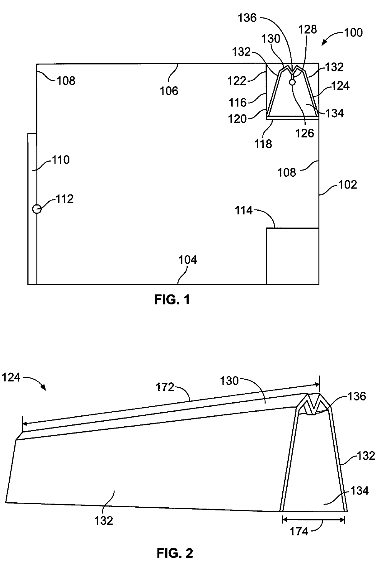
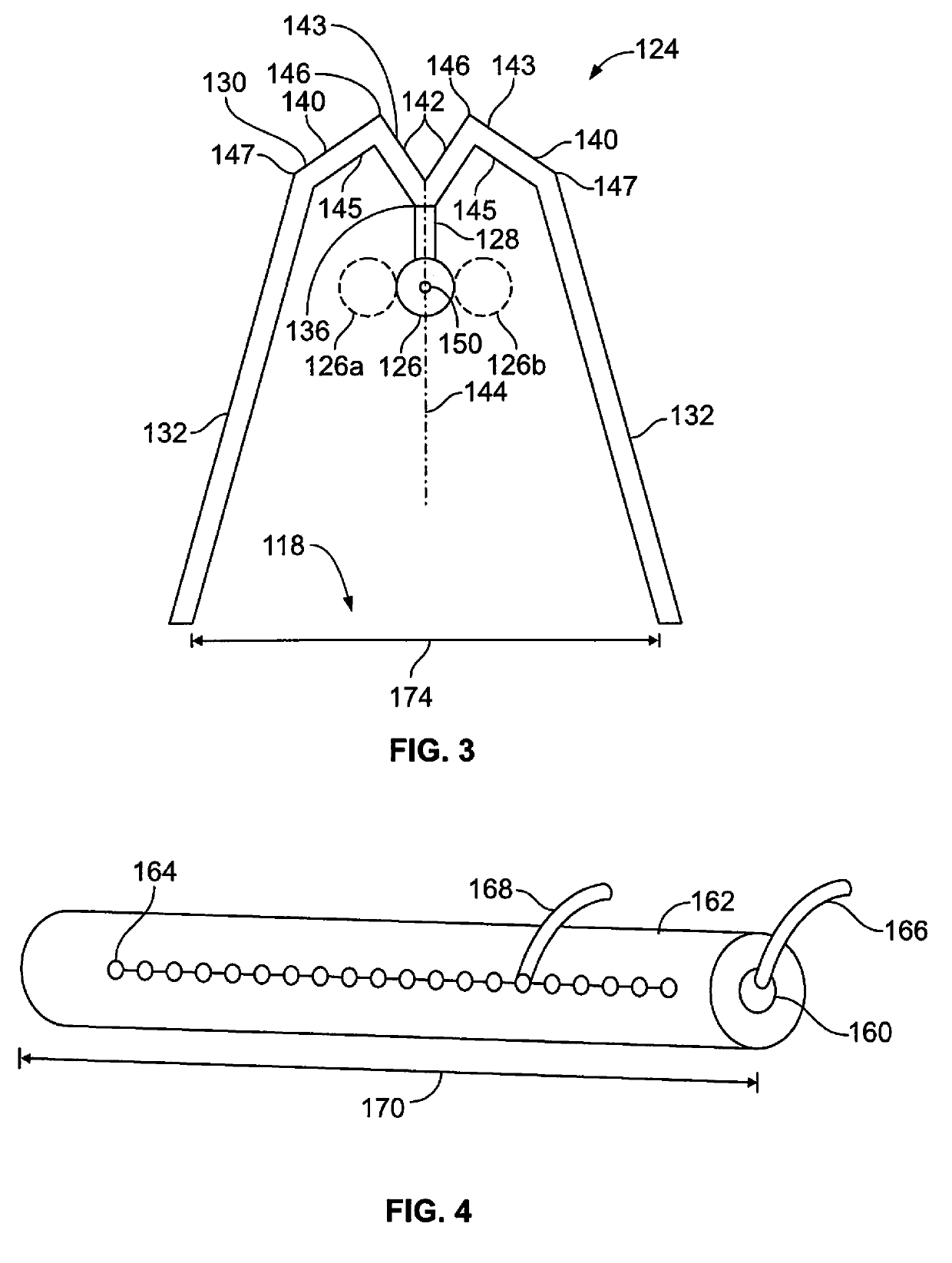
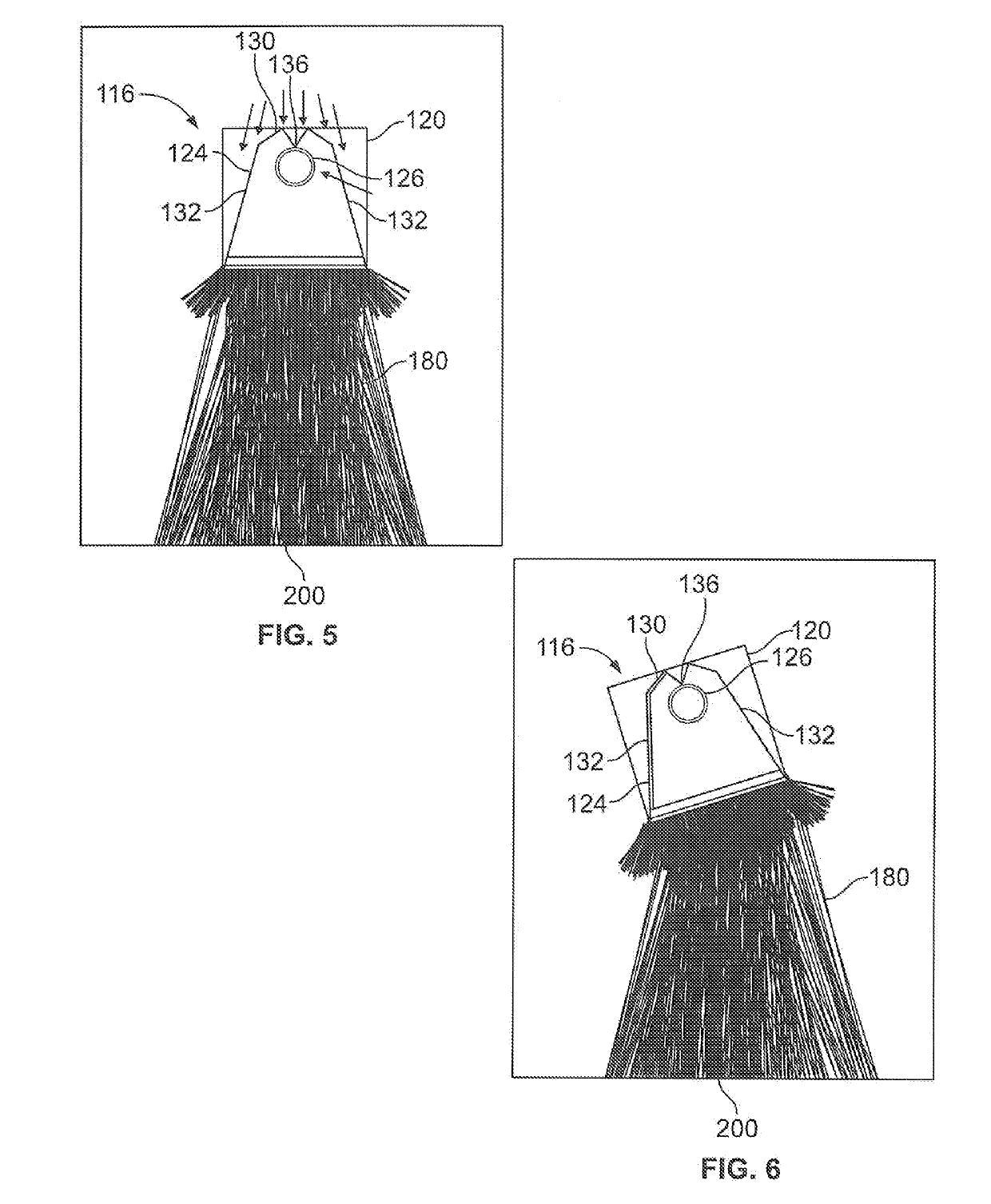
The patent describes a need for a reflector system that can better spread UV light over a surface, as well as a more efficient and compact reflector system that can be used in tight spaces. The patent also proposes a UV lamp reflector that reduces the amount of light reflected back into the bulb and increases the amount of light directed out of the reflector. To address these needs, the patent presents a lighting assembly that includes a reflector system with a central crest that directs emitted light away from the light source to prevent it from reflecting back into the light source.

Problems solved by technology

Many UV light sources are relatively large and bulky, and may be difficult to integrate into a confined space of an aircraft lavatory.
The relatively large reflectors occupy significant space.
As can be appreciated, however, space within an aircraft is limited, and certain UV light assemblies may be too large to integrate into a particular area of the aircraft.
Further, the process of manufacturing curved reflectors is often time and labor intensive, and even more so for reflectors that are to be used with UV light sources, particularly at UVC wavelengths (200-280 nm).

Method used


Image

  • Reflector system for a lighting assembly
  • Reflector system for a lighting assembly
  • Reflector system for a lighting assembly

Examples


Embodiment Construction

[0024]The foregoing summary, as well as the following detailed description of certain embodiments will be better understood when read in conjunction with the appended drawings. As used herein, an element or step recited in the singular and preceded by the word “a” or “an” should be understood as not necessarily excluding the plural of the elements or steps. Further, references to “one embodiment” are not intended to be interpreted as excluding the existence of additional embodiments that also incorporate the recited features. Moreover, unless explicitly stated to the contrary, embodiments “comprising” or “having” an element or a plurality of elements having a particular condition may include additional elements not having that condition.

[0025]Certain embodiments of the present disclosure provide a lighting assembly including a reflector system that is configured to efficiently direct light from a light source onto a surface. The reflector system is configured to redirect light from ...


PUM


Abstract

A lighting assembly includes a light source, such as an ultraviolet (UV) light source that is configured to emit UVC light, and a reflector system including a base having an internal central crest that is configured to direct emitted light away from the light source.

Description

FIELD OF THE DISCLOSURE[0001]Embodiments of the present disclosure generally relate to lighting assemblies, and, more particularly, to ultraviolet (UV) light-emitting assemblies having reflector systems that are configured to efficiently direct UV light onto a surface.BACKGROUND OF THE DISCLOSURE[0002]Commercial aircraft are used to transport passengers between various locations. A typical commercial aircraft includes one or more lavatories within an internal cabin.[0003]Systems are currently being developed to disinfect or otherwise sanitize surfaces within aircraft lavatories that use ultraviolet (UV) light. It has been found that far UV light efficiently disinfects exposed surfaces within a lavatory. UVC light is also used to disinfect exposed surfaces.[0004]In order to effectively sanitize a surface within a lavatory, a UV lighting assembly may be fixed in close proximity to the surface. For example, a UV lighting assembly may be spaced from a toilet within a lavatory a distance...

Claims


Application Information

Patent Timeline
IPC IPC(8): A61L2/10F21V7/05
CPCG02B5/09A61L2/0047F21V7/04F21V19/00A61L2/10A61L2202/25
Inventor GROSS, ADAM FRANKLINCUI, SHANYINGNEFF, BRIAN WAYNEGEARY, KEVINKEEFE, ANDREW C.CAMP, III, RANDOLPH C.CALLAHAN, KEVIN S.CHILDRESS, JAMIE J.
Owner THE BOEING CO
Learn More