
Gravure printing plate and method for producing gravure printing plate

a gravure printing plate and gravure printing technology, which is applied in the direction of printing, printing process, printing, etc., can solve the problems of ink transfer inferiority of etching process and ink blockage of ink, and achieve fine tone settings and increase the density range.

Inactive Publication Date: 2019-04-11
THINK LABORATORY CO LTD
View PDF5 Cites 0 Cited by
  • Summary
  • Abstract
  • Description
  • Claims
  • Application Information

AI Technical Summary

Benefits of technology

[0006]The inventor of the present invention has pursued extensive studies and eventually found that the density range can further be increased and therefore fine tone settings can be performed by combining the FM screen cells with the AM screen cells and varying the depths thereof. Thus, the present invention has been attained.
[0007]The present invention has been made in view of the above-mentioned problem inherent in the conventional technology, and it is therefore an object thereof to provide a gravure printing plate and a method of manufacturing a gravure printing plate, which are capable of increasing a density range as compared to the conventional case to enable suppression of moire as well as to achieve rich gradation and enable fine tone settings.
[0010]Further, it is preferred that a surface area of each of the main cells is larger than a surface area of each of the subcells. That is, it is preferred that the main cells be larger in depth and surface area, and the subcells be smaller in depth and surface area, by which the density range can be increased.
[0022]The present invention has a significant effect in that it is possible to provide a gravure printing plate and a method of manufacturing a gravure printing plate, which are capable of increasing a density range as compared to the conventional case to enable suppression of moire as well as to achieve rich gradation and enable fine tone settings.

Problems solved by technology

In the etching process, the cells are each formed as a depression having a shallow dish shape, and hence ink may be clogged in the cells in a highlight part where the cells are extremely small.
For this reason, the etching process is inferior to the engraving process in terms of the ink transfer.

Method used


Image

  • Gravure printing plate and method for producing gravure printing plate
  • Gravure printing plate and method for producing gravure printing plate
  • Gravure printing plate and method for producing gravure printing plate

Examples


example 1

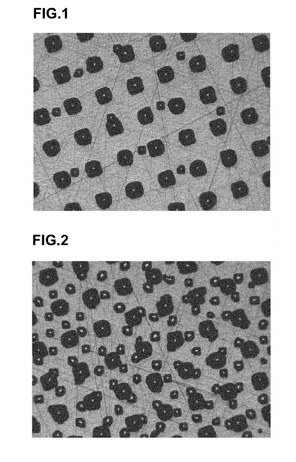
[0051]Laser platemaking was performed with use of a laser gravure platemaking apparatus manufactured by THINK LABORATORY Co., Ltd. (product name: fully automatic laser gravure platemaking system FX80) to manufacture a gravure plate in which FM screen cells formed in the ratio of 1% and at the depth of 3 μm were set as subcells, and AM screen cells formed in the ratio of 10% and at the depth of 15 μm were set as main cells. The main cells and the subcells were positionally aligned at the time of exposure. FIG. 1 shows a plate surface of the gravure plate thus manufactured. In the plate surface of FIG. 1, cells having a larger size are the AM screen cells, and cells having a smaller size are the FM screen cells. When printing was performed with use of the gravure plate thus manufactured, the printed product exhibited slightly higher tone values than in a case of using a plate including only AM screen cells in the ratio of 10%, and the range of gradation was increased. Moire was not ob...

example 2

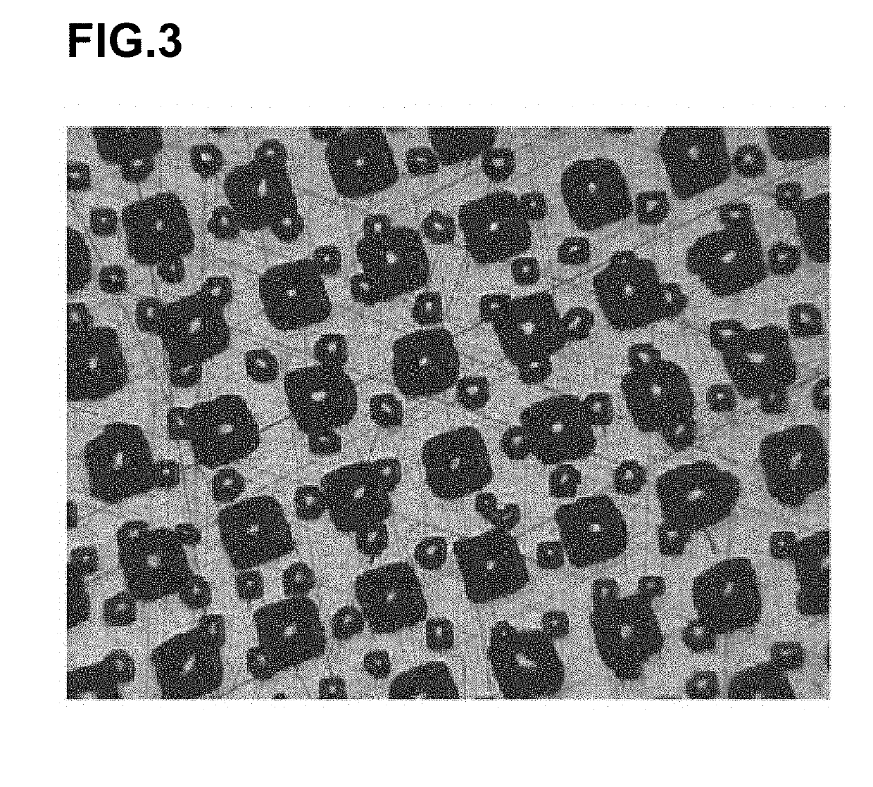
[0052]Similarly to Example 1, a gravure plate was manufactured, in which FM screen cells formed in the ratio of 10% and at the depth of 3 μm were set as subcells, and AM screen cells formed in the ratio of 10% and at the depth of 15 μm were set as main cells. FIG. 2 shows a plate surface of the gravure plate thus manufactured. In the plate surface of FIG. 2, cells having a larger size are the AM screen cells, and cells having a smaller size are the FM screen cells. When printing was performed with use of the gravure plate thus manufactured, the printed product exhibited slightly higher tone values than in the case of using the gravure plate of Example 1, and the range of gradation was increased. Moire was not observed.

example 3

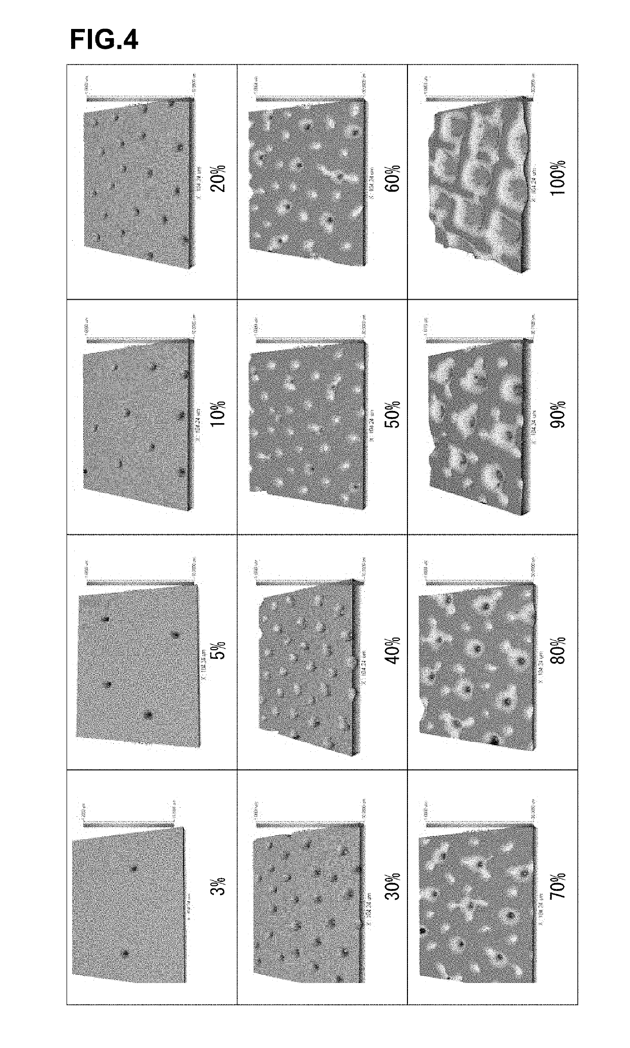
[0053]Similarly to Example 1, a gravure plate was manufactured, in which FM screen cells formed in the ratio of 10% and at the depth of 3 μm were set as subcells, and AM screen cells formed in the ratio of 20% and at the depth of 15 μm were set as main cells. FIG. 3 shows a plate surface of the gravure plate thus manufactured. In the plate surface of FIG. 3, cells having a larger size are the AM screen cells, and cells having a smaller size are the FM screen cells. When printing was performed with use of the gravure plate thus manufactured, the printed product exhibited slightly higher tone values than in a case of using a plate including only AM screen cells in the ratio of 20%, and the range of gradation was increased. Moire was not observed.


PUM


Abstract

A gravure printing plate and a method of manufacturing a gravure printing plate, which are capable of increasing a density range as compared to the conventional case to enable suppression of moire as well as to achieve rich gradation and enable fine tone settings. The gravure printing plate includes FM screen cells and AM screen cells which are concurrently formed in a plate surface thereof, and the FM screen cells and the AM screen cells are different in depth. It is preferred that, of the cells which are different in depth, shallower cells correspond to subcells and deeper cells correspond to main cells.

Description

CROSS REFERENCE TO RELATED APPLICATIONS[0001]This application is a divisional under 37 CFR 1.53(b) of pending prior U.S. application Ser. No. 13 / 639,036 filed Oct. 2, 2012 and claims the benefit (35 U.S.C. § 120 and 365(c)) of International Application PCT / JP2011 / 066037 filed Jul. 14, 2011, which designated inter alia the United States and which claims the priority of Japanese patent application number 2010-176307 filed Aug. 5, 2010, the entire contents of each application are incorporated herein by reference.FIELD OF THE INVENTION[0002]The present invention relates to a gravure printing plate and a method of manufacturing a gravure printing plate, which are capable of increasing a density range as compared to a conventional case to enable fine tone settings.BACKGROUND OF THE INVENTION[0003]Cells of gravure plates are formed by a method involving an engraving process or a method involving photosensitive film application, exposure, development, and etching (etching process). In the m...

Claims


Application Information

Patent Timeline
Patent Type & Authority Applications(United States)
IPC IPC(8): B41C1/05B41C1/18B41N1/06
CPCB41C1/05B41C1/188B41N1/06Y10T428/24479
Inventor SHIGETA, TATSUO
Owner THINK LABORATORY CO LTD
Learn More