Shock absorber

a technology of shock absorber and shock absorber, which is applied in the direction of shock absorber, spring/damper functional characteristics, transportation and packaging, etc., can solve the problems of high cost of components, and achieve the effects of reducing cost, high processing accuracy, and low cos

Inactive Publication Date: 2019-04-11
KYB CORP
View PDF13 Cites 2 Cited by
  • Summary
  • Abstract
  • Description
  • Claims
  • Application Information

AI Technical Summary

Benefits of technology

[0006]Here, an object of the invention is to provide a shock absorber capable of exerting a damping force in response to a frequency and reducing cost.
[0007]In order to solve the above-described problems, the invention includes a damping passage that communicates two operation chambers defined by a piston, a pressure chamber that communicates with the two operation chambers, and an elastic member that defines the pressure chamber as a first chamber communicating with the one operation chamber and a second chamber communicating with the other operation chamber. According to the configuration, when the shock absorber performs the extension and compression operations, the elastic member is elastically deformed so that the volume ratio between the first chamber and the second chamber changes and the liquid inside the pressure chamber flows into and out of the first chamber and the second chamber n response to the amount of elastic deformation, and thus the liquid apparently has moved between two operation chambers through the pressure chamber. In addition, since a partition wall defining the pressure chamber is formed as the elastic member so that the partition wall does not slide, high processing accuracy is not required and components can be provided at low cost.

Problems solved by technology

Since high processing accuracy is required for a sliding portion in which two members slide on each other, the components are expensive.

Method used


Image

  • Shock absorber
  • Shock absorber
  • Shock absorber

Examples


first embodiment

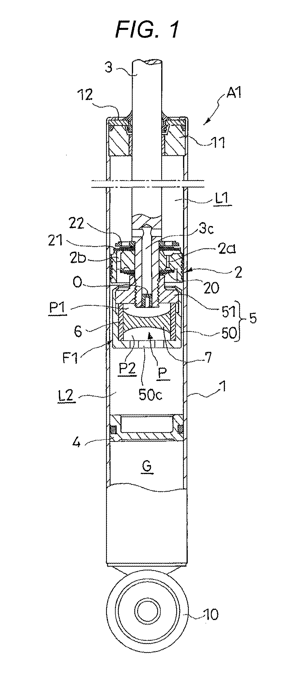
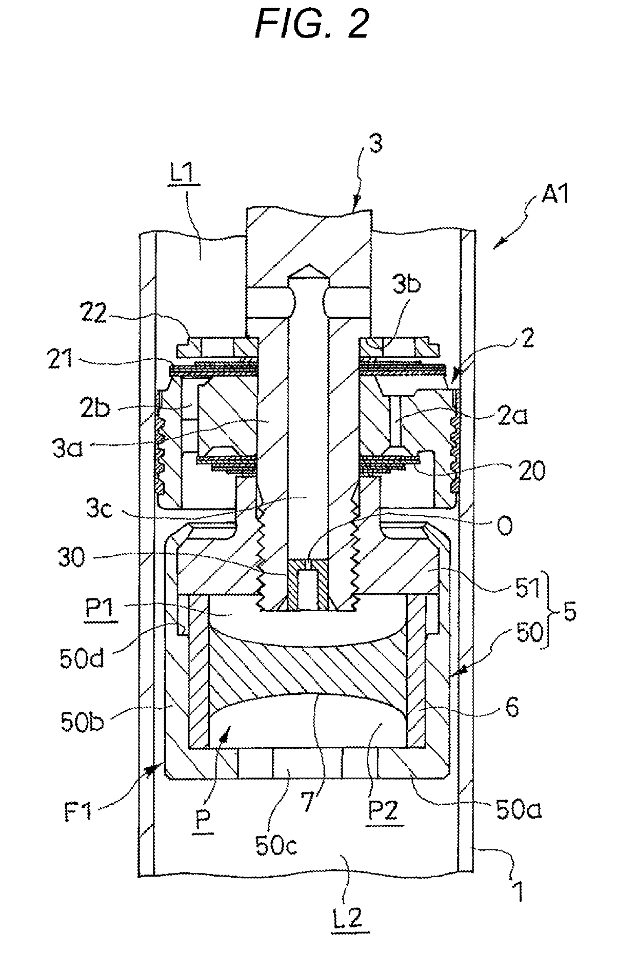
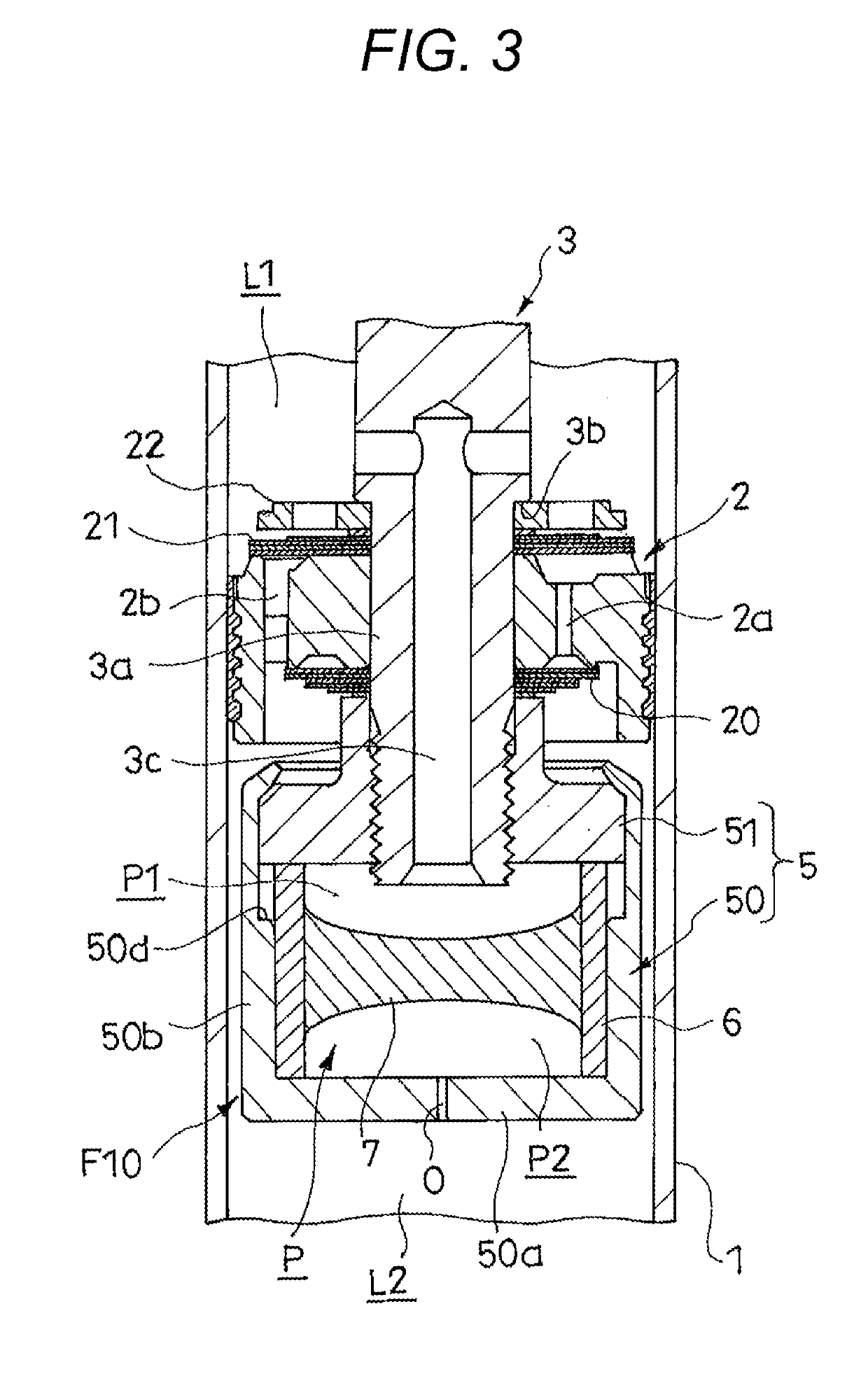
[0015]A shock absorber A1 according to a first embodiment of the invention illustrated in FIG. 1 exerts a damping force while being interposed between a vehicle body and an axle of a vehicle and suppresses a vibration of the vehicle body. The shock absorber A1 includes a cylinder 1, a piston 2 that is slidably inserted into the cylinder 1, a piston rod 3 of which one end is connected to the piston 2 and the other end extends to the outside of the cylinder 1, a frequency sensitive portion F1 that is attached to the lower side of the piston 2 of the piston rod 3 of FIG. 1, and a sliding partition wall 4 that is slidably inserted to the opposite piston rod side inside the cylinder 1.

[0016]Then, the cylinder 1 is connected to one of the vehicle body and the axle through the attachment member 10 and the piston rod 3 is connected to the other of the vehicle body and the axle through an attachment member (not illustrated). Thus, when the vehicle body and the axle move away from each other,...

second embodiment

[0041]Similarly to the shock absorber A1 according to the first embodiment, a shock absorber A2 according to a second embodiment of the invention illustrated in FIG. 4 suppresses the vibration of the vehicle body by exerting the damping force while being interposed between the vehicle body and the axle of the vehicle. The shock absorber A2 of the embodiment has the same basic configuration and operation as those of the shock absorber A1 and has a difference in the position of the frequency sensitive portion. Thus, a configuration of the different portion will be described in detail below. Further, the same reference numerals will be given to the common components and a detailed description thereof will be omitted.

[0042]In the shock absorber A2 according to the embodiment, a frequency sensitive portion F2 is provided on the side of the extension side chamber L1 of the piston 2 and a housing 8 of the frequency sensitive portion F2 constitutes a part of the piston rod 3. Specifically, ...


PUM


Abstract

A shock absorber includes: a cylinder; a piston that is movably inserted into the cylinder and defines an extension side chamber and a compression side chamber inside the cylinder; an extension side damping passage and a compression side damping passage that communicate the extension side chamber with the compression side chamber; a pressure chamber that communicates with the extension side chamber and the compression side chamber; and an elastic member that defines a first chamber communicating with the extension side chamber and a second chamber communicating with the compression side chamber inside the pressure chamber.

Description

TECHNICAL FIELD[0001]The present invention relates to a shock absorber.BACKGROUND ART[0002]Conventionally, a shock absorber is interposed between a vehicle body and an axle of a vehicle and is used to suppress a vibration of the vehicle body. For example, as disclosed in JP 4644572 (B2) and JP 4726049 (B2), the shock absorber includes a cylinder, a piston that is slidably inserted into the cylinder, a piston rod of which one end is connected to the piston and the other end extends to the outside of the cylinder, upper and lower chambers that are formed inside the cylinder and defined by the piston, first and second passages that communicate with the upper and lower chambers, a pressure chamber that is provided in the course of the second passage, a housing that has a pressure chamber formed therein and is attached to a front end of the piston rod, a free piston that is slidably inserted into the housing and defines the pressure chamber as one chamber communicating with the lower cha...

Claims


Application Information

Patent Timeline
Patent Type & Authority Applications(United States)
IPC IPC(8): F16F9/512F16F9/19F16F9/32B60G13/08B60G17/08
CPCF16F9/512F16F9/19F16F9/3214B60G13/08B60G17/08F16F9/061F16F9/065F16F9/182F16F9/3271F16F9/3228F16F2228/066B60G2206/41B60G2500/10F16F2228/04F16F9/3207F16F9/32
Inventor INAMITSU, KAZUTAKATERAOKA, TAKASHI
Owner KYB CORP
Why Eureka
Try Eureka