Build-up welding method

a build-up welding and welding method technology, applied in the field of build-up welding methods, can solve the problems of high penetration depth, sharp limit in the guide speed of such build-up welding methods, and increase the melting of the workpiece, so as to achieve the effect of low penetration depth, high melting of the vertically underlying layer, and durable production of flat materials

Pending Publication Date: 2019-04-18
PLASCH SIEGFRIED
View PDF129 Cites 0 Cited by
  • Summary
  • Abstract
  • Description
  • Claims
  • Application Information

AI Technical Summary

Benefits of technology

The patent describes a new welding method for producing durable material buildup with good connection to the base material and minimal change in material properties. The method involves guiding a non-melting electrode along the workpiece to achieve a homogeneous arc and uniform melting of the wire. By moving the welding wire back and forth along its infeed direction, penetration depth into the workpiece can be controlled, reducing material mixing. The combination of the electrode position and wire movement results in high build-up speeds, outperforming existing methods, and retaining favorable material properties. Increasing the wire temperature further improves performance.

Problems solved by technology

The guidance speed of such build-up welding methods, however, is sharply limited since an increase in the guidance speed results in a breakage of the welding bead.
On the other hand, an increase in the diameter of the non-melting electrode results in a more pronounced melting of the workpiece (a higher penetration depth) and thus in an undesirable mixing between the build-up material and the workpiece, which has a negative impact on the material properties of the build-up material.
On the other hand, a guidance speed that is too slow results in the formation of a large molten puddle and accompanying formation of droplets.

Method used


Image

  • Build-up welding method
  • Build-up welding method
  • Build-up welding method

Examples


Embodiment Construction

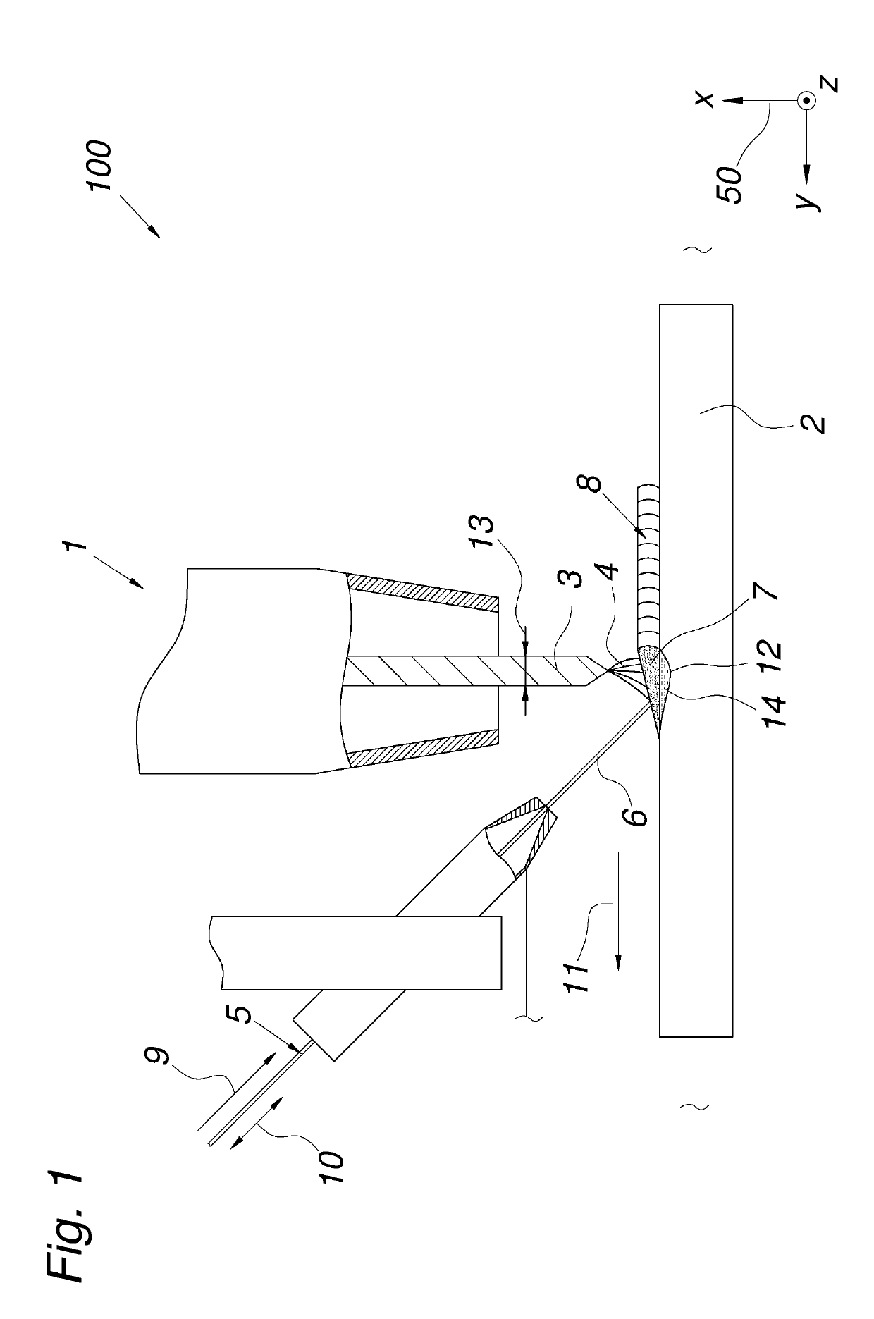
[0003]The stated object of the invention is to increase the speed of the build-up welding method while simultaneously achieving a low penetration depth.

[0004]The invention attains the stated object in that the non-melting electrode, positioned normal to the workpiece, is guided along the workpiece and the fed wire is additionally moved back and forth along its infeed direction.

[0005]If the non-melting electrode, positioned normal to the workpiece, is guided along the workpiece, then it is possible to achieve a particularly homogeneous arc, which enables an improved, namely uniform, melting of the wire. In addition, through the placement of the non-melting electrode normal to the workpiece in a PC welding position, a capillary action on the melt can be achieved, advantageously making it possible to avoid a formation of droplets from the melt. If the fed wire is additionally moved back and forth along its infeed direction, then the penetration depth into the workpiece can be reduced i...


PUM

PropertyMeasurementUnit
diameteraaaaaaaaaa
speedaaaaaaaaaa
infeed speedaaaaaaaaaa

Abstract

A build-up welding method (100) is disclosed in which a welding torch (1) is guided along a metallic workpiece (2) and at least one melting wire (5) serving as a build-up material (6) is fed at an infeed speed (9) into the arc (4) between at least one non-melting electrode (3) of the welding torch (1) and the workpiece (2). In order to achieve a build-up welding method (100) with higher build-up speeds in comparison to the prior art, it is proposed for the non-melting electrode (3) positioned normal to the workpiece (2) to be guided along the workpiece (2) and for the fed wire (5) to also be moved back and forth along its infeed direction (9).

Description

TECHNICAL FIELD[0001]The invention relates to a build-up welding method in which a welding torch is guided along a metallic workpiece and at least one melting wire serving as a build-up material is fed at an infeed speed into the arc between at least one non-melting electrode of the welding torch and the workpiece.PRIOR ART[0002]In the prior art, there are known build-up welding methods in the DIN EN ISO 6947-specified PC welding position (ASME: 2G) in which a welding torch (e.g.: WIG torch) is guided horizontally along a vertically oriented, fixed metallic workpiece (e.g.: a pipe). In this case, a wire (e.g.: hot wire) is fed at a continuous infeed speed into an arc, which is produced by a non-melting electrode (e.g.: tungsten electrode) positioned obliquely to the guidance direction of the welding torch, and is melted in order to achieve a welding build-up on the material. The guidance speed of such build-up welding methods, however, is sharply limited since an increase in the gui...

Claims


Application Information

Patent Timeline
Patent Type & Authority Applications(United States)
IPC IPC(8): B23K9/04B23K9/12B23K9/167
CPCB23K9/048B23K9/124B23K9/167B23K2101/06
Inventor PLASCH, SIEGFRIED
Owner PLASCH SIEGFRIED
Why Eureka
Try Eureka