
Hydraulic mount having unidirectional damping membrane

a technology of damping membrane and hydraulic mount, which is applied in the direction of shock absorber, jet propulsion mounting, transportation and packaging, etc., can solve the problems of disadvantageous damping characteristics, fluid engine mount disadvantages, and occupants' bodies may be seriously injured, so as to improve the damping force and prevent vibration

Active Publication Date: 2019-04-18
HYUNDAI MOTOR CO LTD +1
View PDF10 Cites 1 Cited by
  • Summary
  • Abstract
  • Description
  • Claims
  • Application Information

AI Technical Summary

Benefits of technology

The patent text discusses the advantages and disadvantages of two types of engine mounts: rubber and fluid. The rubber mount is cheaper but has poor damping characteristics, while the fluid mount is expensive but effective at insulating vibration and noise. The text also mentions that a one-way closure means can shift the mount's resonance region to a lower frequency, making it easier to separate from vehicle vibrations. The technical effects of this patent text are that it provides a cost-effective solution for insulating vibration and noise, and it enhances the mount's damping characteristics to reduce vehicle vibrations.

Problems solved by technology

The vibration transferred to the vehicle interior causes discomfort to an occupant and degrades a pleasant driving environment, and an occupant's body may be seriously injured if the vibration is intense.
The rubber engine mount is inexpensive compared to a fluid engine mount but disadvantageous in damping characteristics.
The fluid engine mount has an advantage because the fluid engine mount insulates vibration and noise by means of a damping effect in respect to a fluid mass, but the fluid engine mount is disadvantageous because the fluid engine mount is expensive.
The air damper mount is disadvantageous in terms of costs compared to the rubber engine mount but advantageous in terms of costs compared to the fluid engine mount, and the air damper mount is disadvantageous in terms of performance compared to the fluid engine mount but advantageous in terms of performance compared to the rubber engine mount.
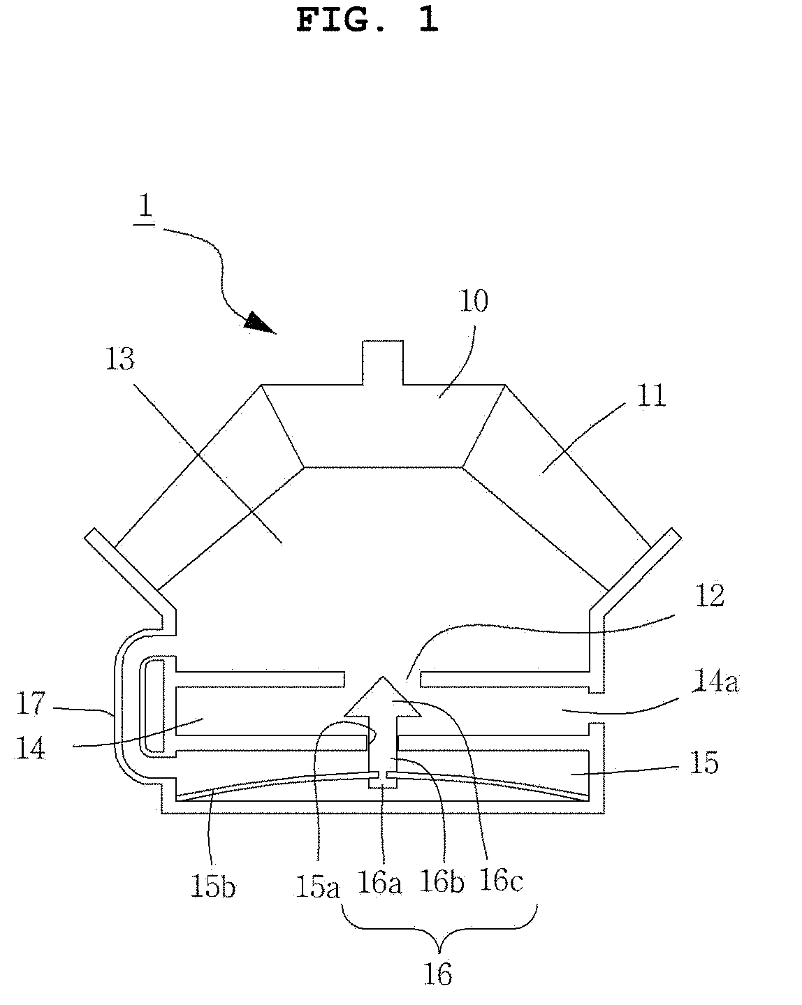
However, the diaphragm portion 15b receives pressure of the fluid flowing from the upper chamber 13 or the rigid chamber 15 since the control rod 16 is integrated with the diaphragm portion 15b, and in this case, an operating unit 16c having a conical shape tends not to properly block the installation hole 15a due to unbalance of liquid pressure or the like.

Method used


Image

  • Hydraulic mount having unidirectional damping membrane
  • Hydraulic mount having unidirectional damping membrane
  • Hydraulic mount having unidirectional damping membrane

Examples


Embodiment Construction

[0034]Hereinafter, embodiments of the present invention will be described in detail with reference to the accompanying drawings so that those skilled in the art to which the present invention pertains may easily carry out the present invention. However, the present invention may be implemented in various different ways, and is not limited to embodiments described herein.

[0035]A part irrelevant to the description will be omitted to clearly describe embodiments of the present invention, and the same or similar constituent elements will be designated by the same reference numerals throughout the specification.

[0036]Terms or words used in the specification and the claims should not be interpreted as being limited to a general or dictionary meaning and should be interpreted as a meaning and a concept which conform to the technical spirit of the present invention based on a principle that an inventor can appropriately define a concept of a term in order to describe his / her own invention b...


PUM


Abstract

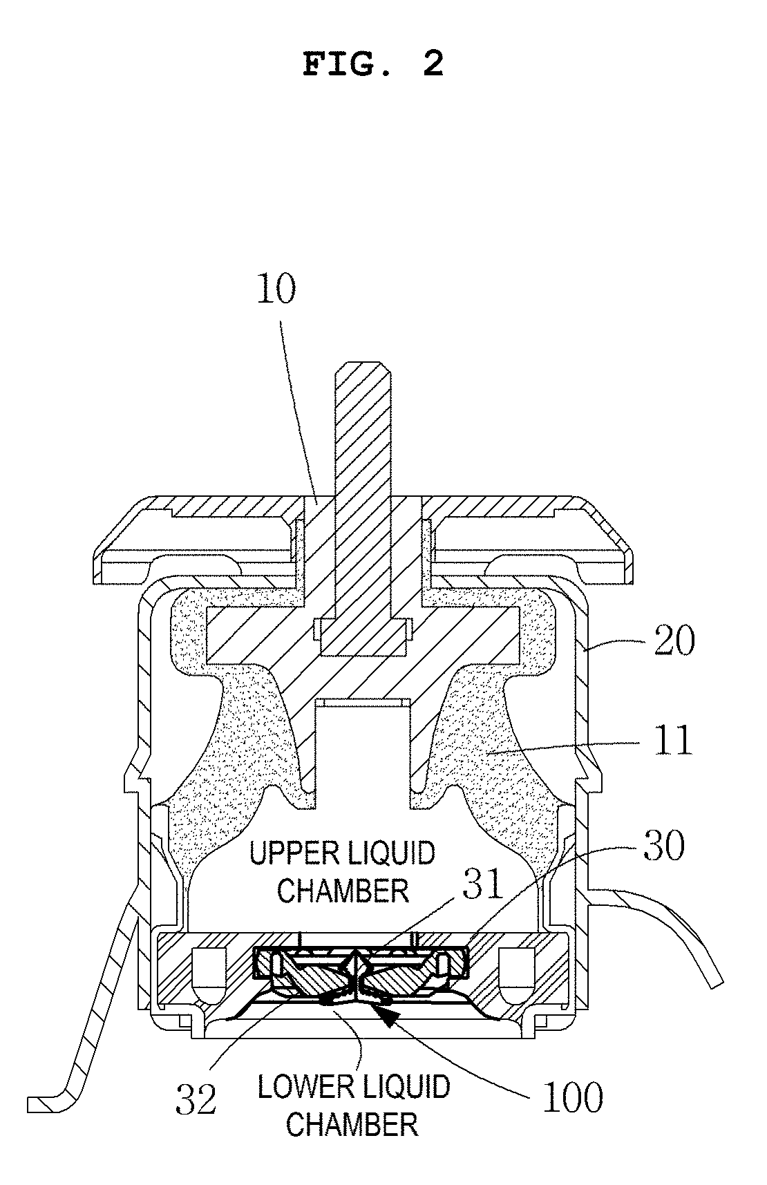
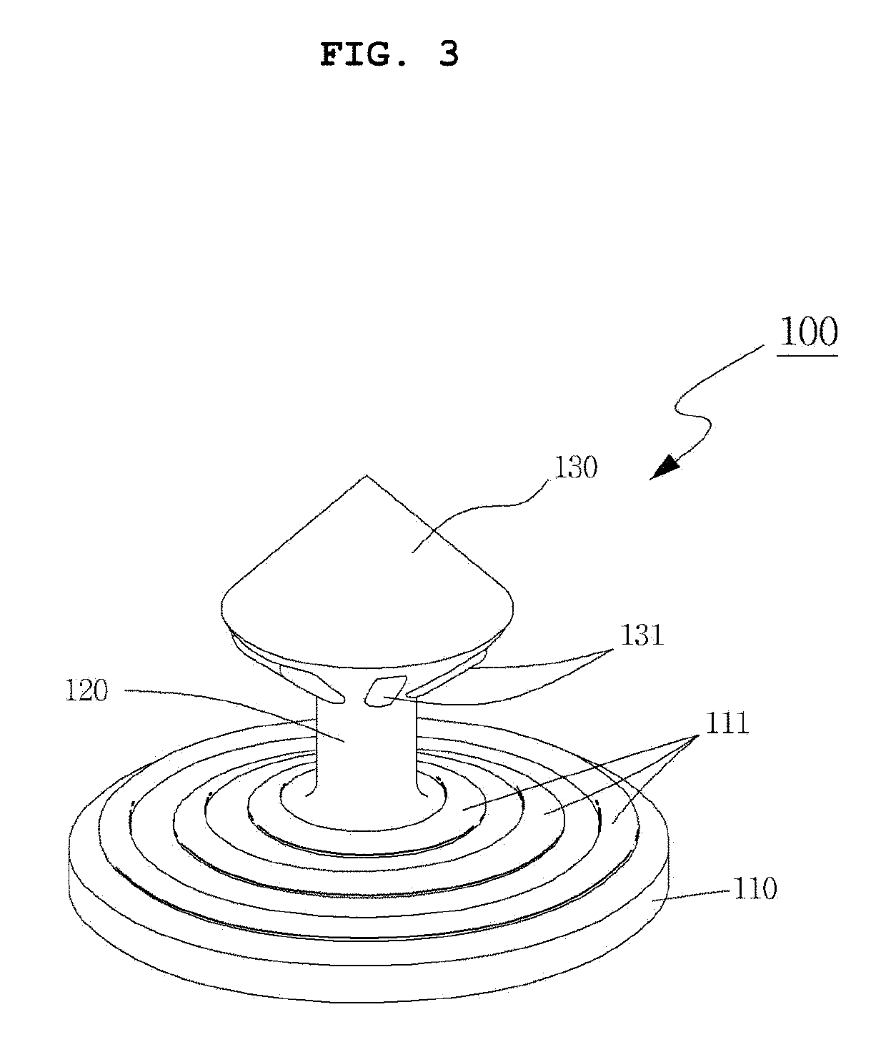
The present disclosure relates to a hydraulic mount having a unidirectional damping membrane. A hole is formed in a membrane and a one-way closure having upper and lower portions, which are different from each other, is inserted into the hole to control a flow of a fluid. The one-way closure means includes: a body which intermittently closes a lower side of the hole formed at a center of the membrane; a column portion which is vertically formed at a center of the body; and a moving closure which is formed at an upper portion of the column portion and closes an upper side of the hole.

Description

CROSS-REFERENCE TO RELATED APPLICATIONS[0001]This application claims priority under 35 U.S.C. § 119 to Korean Patent Application No. 10-2017-0133732, filed on Oct. 16, 2017, with the Korean Intellectual Property Office, the disclosure of which is incorporated herein by reference in its entirety.BACKGROUND1. Field[0002]The present disclosure relates to a hydraulic mount having a unidirectional damping membrane.2. Description of the Related Art[0003]In general, an engine of a vehicle always and structurally vibrates due to a periodic change in center position of the engine caused by upward and downward movements of a piston and a connecting rod, and a periodic change in inertial force applied to reciprocating parts in an axial direction of a cylinder, inertial force occurring when the connecting rod is rattled leftward and rightward about a crank shaft, and rotational force applied to the crank shaft.[0004]The causes of the vibration do not act separately but always act in a complex m...

Claims


Application Information

Patent Timeline
Patent Type & Authority Applications(United States)
IPC IPC(8): B60K5/12F16F13/22F16F13/26F16F13/10
CPCB60K5/1208F16F13/22F16F13/26F16F13/10F16F9/3415F16F13/105F16F13/1463F16F13/106B60K5/12
Inventor YUN, JAE-HYUNG
Owner HYUNDAI MOTOR CO LTD
Learn More