Fixing device

a fixing device and end portion technology, applied in the direction of electrographic process equipment, instruments, optics, etc., can solve the problems of degrading the fixability of the above-mentioned end portions, and achieve the effect of improving the fixability of the end portions and reducing the temperature of the non-passing portion

Active Publication Date: 2019-04-18
CANON KK
View PDF1 Cites 6 Cited by
  • Summary
  • Abstract
  • Description
  • Claims
  • Application Information

AI Technical Summary

Benefits of technology

[0005]The present disclosure provides a fixing device that is capable of achieving both a suppression in the sheet non-passing portion temperature increase and an improvement in the end portion fixability.

Problems solved by technology

However, when the heat conducting member is contacted to the heater and the fixing film across the longitudinal direction of the heater and the fixing film, there are cases in which the fixability of end portions of the above becomes degraded due to a decrease in temperature caused by heat radiation from the end portions.
In particular, when a wide recording material is fixed, there are cases in which an offset occurs in the image end portions (hereinafter, described as “offsets in the end portions”) due to insufficient melting of the toner at the image end portion.

Method used


Image

  • Fixing device
  • Fixing device
  • Fixing device

Examples


first exemplary embodiment

[0026]A configuration of a main body of an image forming apparatus according to the present exemplary embodiment will be described first and, then, a fixing device according to the present exemplary embodiment will be described in detail.

(1) Image Forming Apparatus

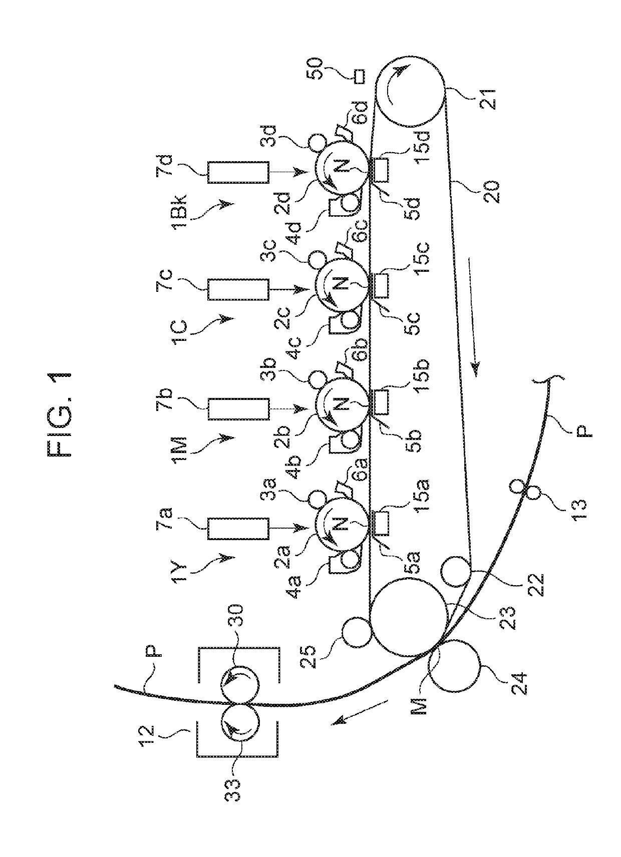
[0027]Referring to FIG. 1, a configuration of an image forming apparatus according to a first exemplary embodiment will be described. FIG. 1 is a schematic block diagram of a typical color image forming apparatus (an intermediate transfer full color printer adopting an electrophotographic printing method in the present exemplary embodiment) according to the first exemplary embodiment of the present disclosure.

[0028]The above color image forming apparatus includes four image forming units 1Y, 1M, 1C, and 1Bk that forms images of yellow, magenta, cyan, and black, respectively. The four image forming units are disposed in a line at uniform intervals.

[0029]Photosensitive drums 2a, 2b, 2c, and 2d serving as image carrying membe...

second exemplary embodiment

[0088]In the present exemplary embodiment, an example in which a configuration using a graphite sheet serving as a high heat conducting member that is different from the aluminum plate used in the first exemplary embodiment has been applied to the present disclosure will be described. The configuration of the image forming apparatus is similar to that of the first exemplary embodiment, which is illustrated in FIG. 1. Accordingly, redundant description will be omitted.

[0089]FIG. 8 is a cross-sectional view illustrating a fixing device of a color image forming apparatus according to a second exemplary embodiment. Description that overlap the first exemplary embodiment will be omitted. The point in the second exemplary embodiment that is different from the first exemplary embodiment, which is the feature of the second exemplary embodiment, is that rather than the aluminum plate 81, a graphite sheet 83 is used. The graphite sheet 83 is formed by two-dimensionally crystallized carbon bei...

third exemplary embodiment

[0097]The present disclosure has been described in the first and second exemplary embodiments using longitudinal length A of area a and longitudinal length B of area b. The above configurations are configurations that can obtain the effect of the present disclosure in both the longitudinal end portions of the image forming apparatus. In the present exemplary embodiment, a configuration in which the effect is obtained on at least either one side (longitudinally one end side) will be described.

[0098]As an example in which the present exemplary embodiment is effectively used, a configuration will be described in which a reference for the conveying (sheet-passing) position is a one-side reference. The configuration of the image forming apparatus is similar to that of the first exemplary embodiment, which is illustrated in FIG. 1. Furthermore, a cross section of the fixing device in the longitudinal direction is similar to that of the first exemplary embodiment, which is as illustrated i...


PUM


Abstract

A fixing device including a rotatable tubular film, a heater including a substrate and a heat generating resistor, the heater including a first surface in contact with an inner surface of the film and a second surface opposite to the first surface, the heater extending in a longitudinal direction of the substrate, and a heat conducting member extending in the longitudinal direction and including a heater contact portion in contact with the second surface. The heat conducting member includes a film contact portion at a position adjacent to the first surface, the film contact portion being in contact with the inner circumferential surface, and on one side in the longitudinal direction, the heat generating resistor extends outside of a longitudinal end portion of the film contact portion, and the heater contact portion extends outside of the film contact portion.

Description

BACKGROUND OF THE INVENTIONField of the Invention[0001]The present disclosure relates to a fixing device used in an image forming apparatus, such as a copier, a printer, or a facsimile, that is equipped with a function of forming an image on a recording material.Description of the Related Art[0002]In fixing devices used in electrophotographic system image forming apparatuses, a fixing device that adopts a film heating method is known. The fixing device includes a tubular fixing film, a plate-shape heater that comes in contact with an inner surface of the fixing film, and a pressure roller that forms a nip portion by contacting an outer surface of the fixing film. A recording material that carries a toner image is conveyed and heated by the nip portion so that the toner image is fixed to the recording material. Since the heat capacity of the fixing film is small in the fixing device adopting the film heating method, the fixing device has advantages such as the warming up time being s...

Claims


Application Information

Patent Timeline
Patent Type & Authority Applications(United States)
IPC IPC(8): G03G15/20
CPCG03G15/2053G03G15/2064G03G15/2028G03G2215/20G03G2215/2016
Inventor AKIZUKI, TOMOOSUZUMI, MASAHIKOKINUKAWA, TATSUYANAKADA, TAKEHARUMORIHARA, RYO
Owner CANON KK
Why Eureka
Try Eureka