
Polyaxial bone anchoring device

Active Publication Date: 2019-04-25
BIEDERMANN TECH GMBH & CO KG
View PDF11 Cites 6 Cited by
  • Summary
  • Abstract
  • Description
  • Claims
  • Application Information

AI Technical Summary

Benefits of technology

The invention provides a polyaxial bone anchoring device that allows for better handling during surgery. The device can be locked and unlocked by moving a clamping ring, which reduces the pressure on the vertebrae and allows for easier handling. The device can also be combined with different anchoring elements to meet different clinical needs, reducing costs and inventory.

Problems solved by technology

Moreover, by locking the rod, pressure exerted by the rod onto the pressure member may further increase the locking force onto the head.

Method used


Image

  • Polyaxial bone anchoring device
  • Polyaxial bone anchoring device
  • Polyaxial bone anchoring device

Examples


Embodiment Construction

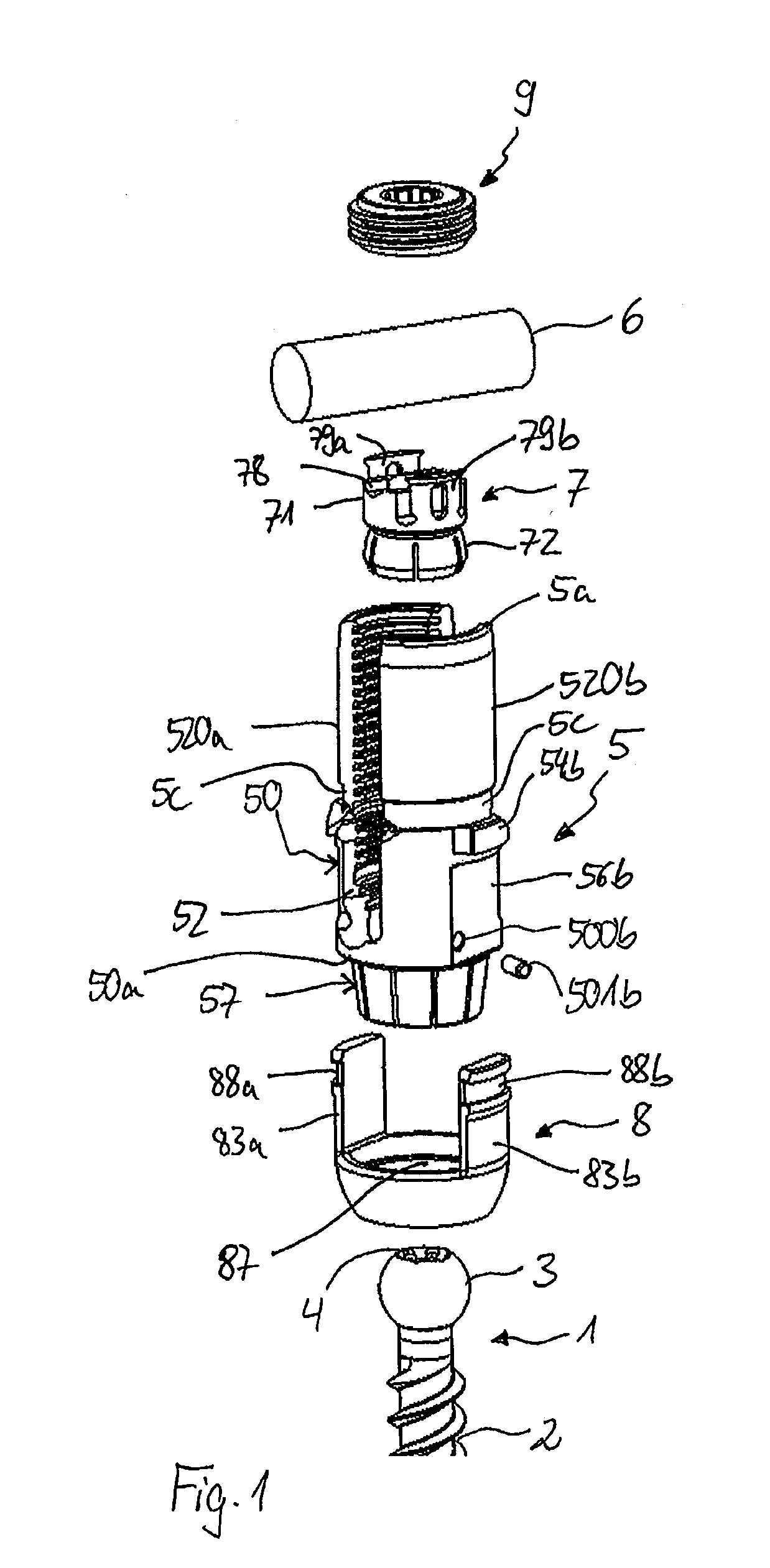
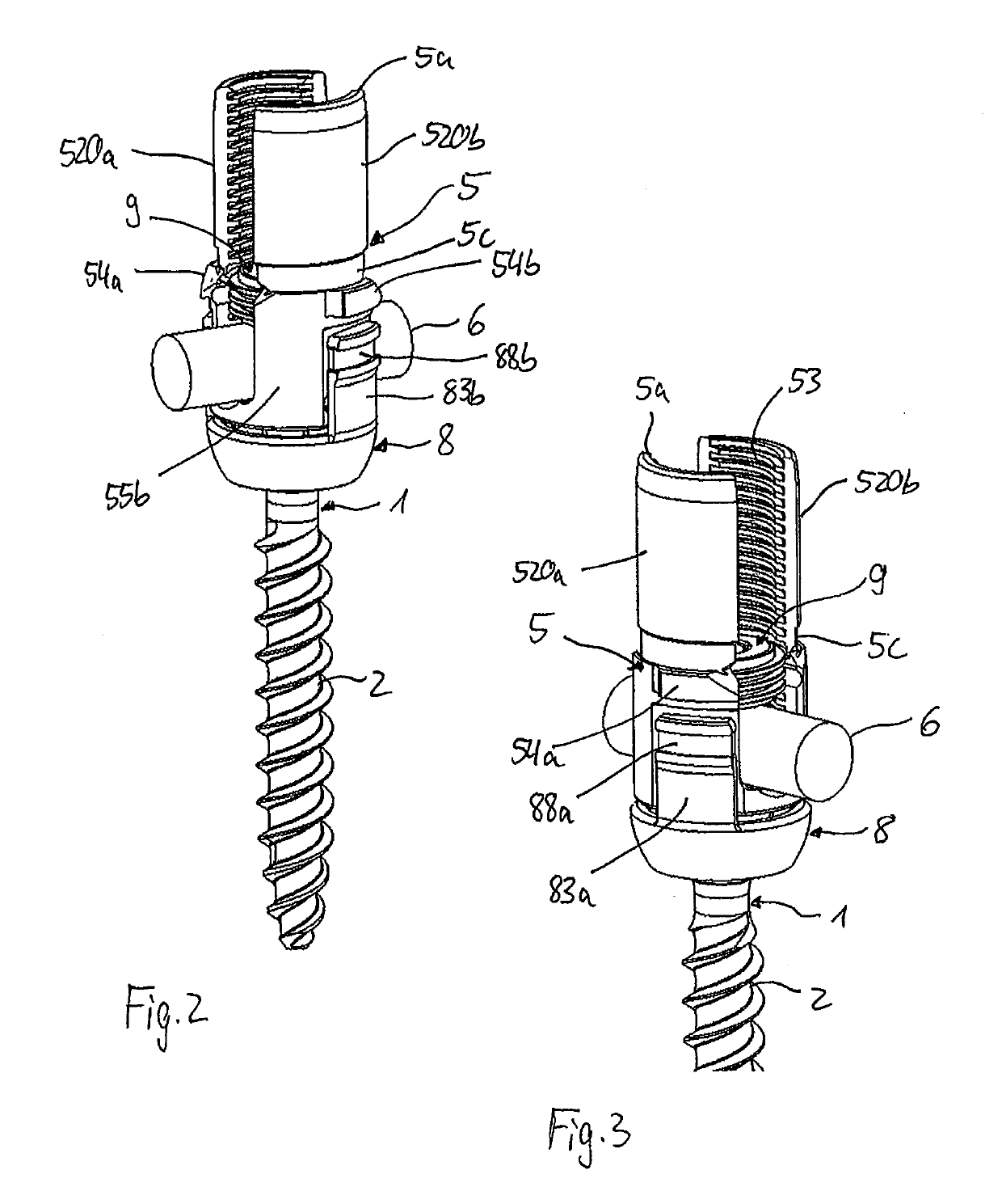
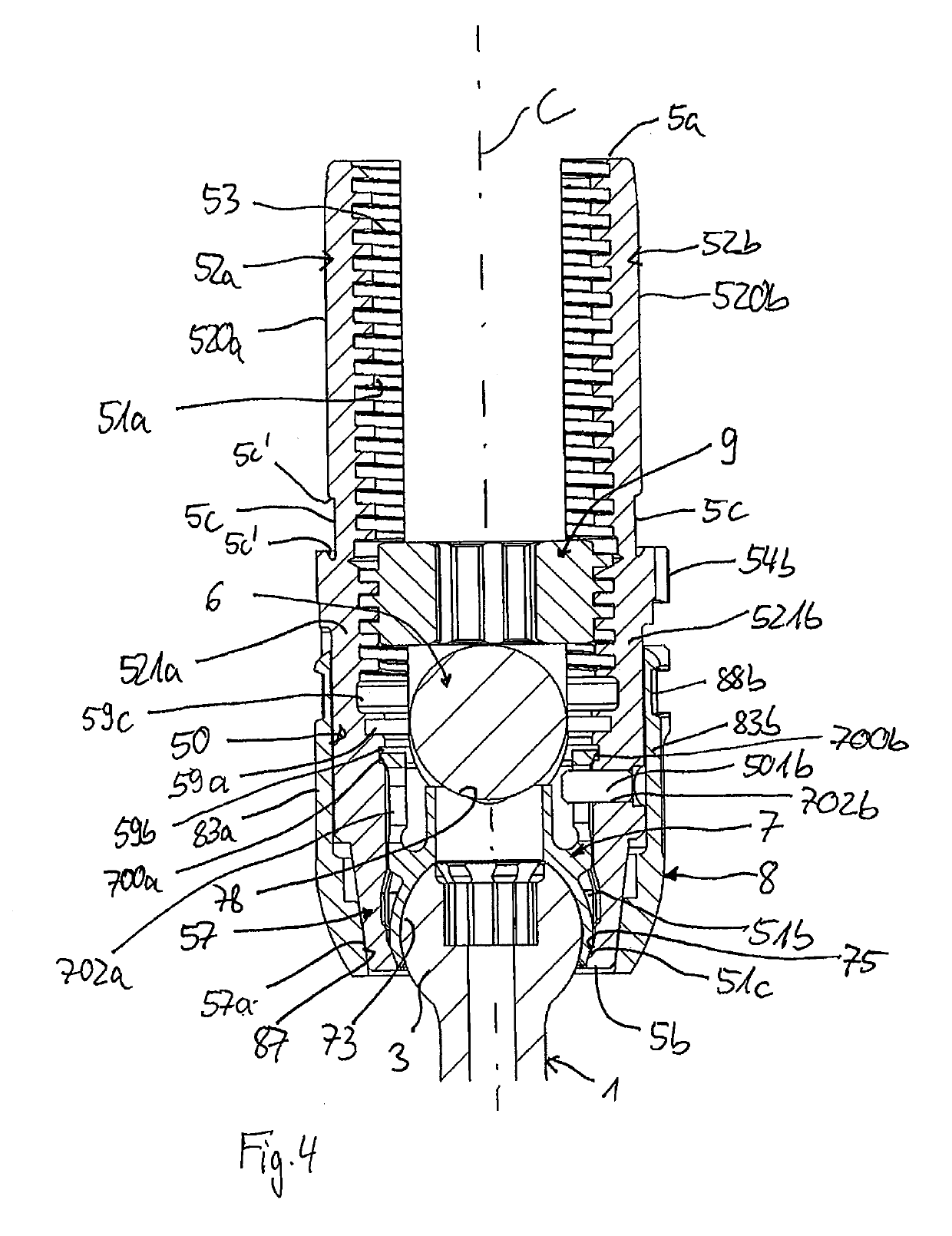
[0040]As shown in FIGS. 1 to 4, a bone anchoring device according to an embodiment of the invention includes a bone anchoring element 1 in the form of, for example, a bone screw having a shank 2 with a threaded portion and a head 3 with a spherically-shaped outer surface portion. The head 3 may have a recess 4 for engagement with a driver or tool. The bone anchoring device also includes a receiving part 5 for receiving a rod 6 to be connected to the bone anchoring element 1. Further, a pressure member 7 may be provided in the receiving part 5 for exerting pressure onto the head 3 of the bone anchoring element 1. In addition, the bone anchoring device includes a clamping ring 8 that is mountable to the receiving part 5 for compressing a portion of the receiving part 5 to exert pressure onto the pressure member 7 and in turn onto the head 3. Lastly, the bone anchoring element also includes a fixation element 9 in the form of, for example, an inner screw or set screw for fixing the rod...


PUM


Abstract

A bone anchoring device includes a receiving part for coupling a rod to a bone anchoring element, the receiving part having a first end, a second end, a recess at the first end for receiving the rod, and a compressible head receiving portion at the second end for accommodating a head of the bone anchoring element, a pressure member positionable in the receiving part to exert pressure on the head, and a clamping ring positionable around the head receiving portion and movable towards the first end of the receiving part to a locking position where the clamping ring exerts force on and compresses the head receiving portion. In the locking position, at least part of the clamping ring that faces the first end of the receiving part is exposed to the outside to facilitate movement of the clamping ring away from the first end of the receiving part.

Description

CROSS-REFERENCE TO RELATED APPLICATION(S)[0001]The present application claims priority to and the benefit of U.S. Provisional Patent Application No. 62 / 576,961, filed Oct. 25, 2017, the contents of which are hereby incorporated by reference in their entirety, and claims priority from European Patent Application EP 17 198 405.5, filed Oct. 25, 2017, the contents of which are hereby incorporated by reference in their entirety.BACKGROUND[0002]The invention relates to a polyaxial bone anchoring device. More specifically, the bone anchoring device includes a receiving part for coupling a rod to a bone anchoring element that has a head to be received in the receiving part, and further includes a clamping ring that is configured to lock and unlock the head in the receiving part, for example by using an instrument.DESCRIPTION OF RELATED ART[0003]U.S. Pat. No. 5,549,608 describes a polyaxial orthopedic device for use with a rod implant apparatus including a screw having a curvate head and a ...

Claims


Application Information

Patent Timeline
IPC IPC(8): A61B17/70A61B17/86
CPCA61B17/7037A61B17/7032A61B17/8605A61B2017/564A61B17/7076A61B17/7086A61B17/7035
Inventor BIEDERMANN, TIMOMATTHIS, WILFRIED
Owner BIEDERMANN TECH GMBH & CO KG
Learn More