Fixation device for pelvis

Inactive Publication Date: 2019-04-25
ZHU XIEPING
View PDF4 Cites 2 Cited by
  • Summary
  • Abstract
  • Description
  • Claims
  • Application Information

AI Technical Summary

Benefits of technology

[0011]The fixation device is easy to use, can quickly form a shape matched with the body, provides satisfactory fixation effect, fully meets the docto

Problems solved by technology

However, all such devices are not ideal.
For example, splints are likely to result in bone displacement; plasters do n

Method used


Image

  • Fixation device for pelvis
  • Fixation device for pelvis

Examples


Example

[0014]The present invention will be further described with reference to the accompanying drawings.

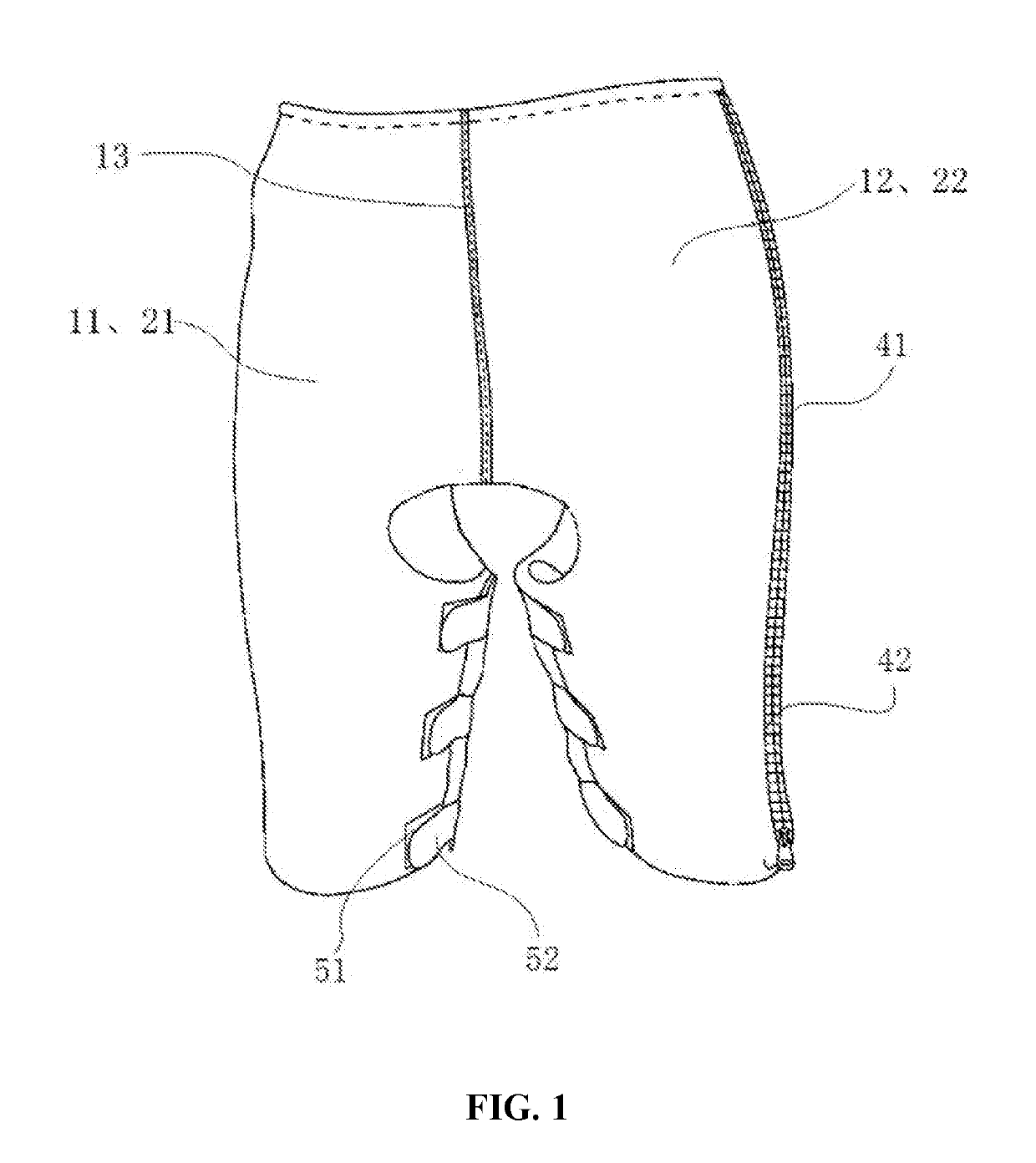
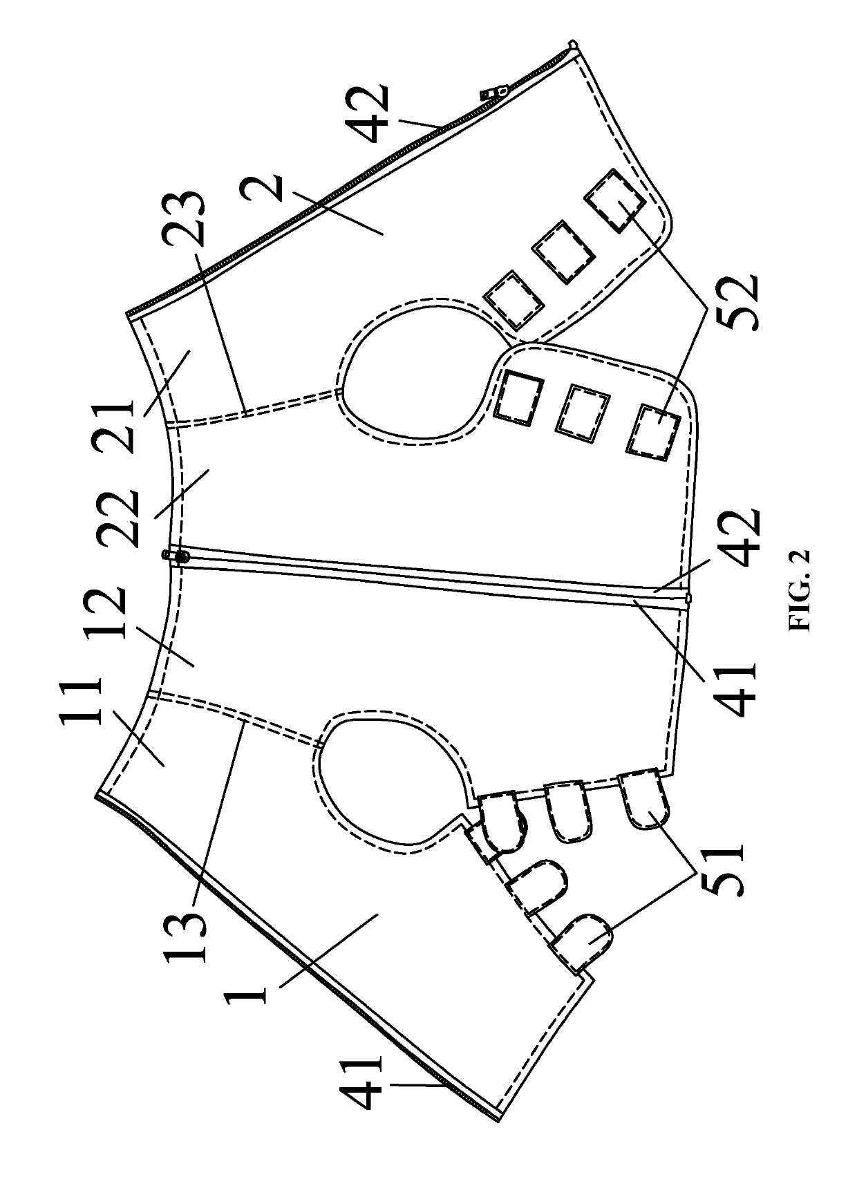
[0015]As shown in FIG. 1 and FIG. 2, a fixation device for pelvis comprises a front fixation plate 1 and a rear fixation plate 2. The front fixation plate 1 and the rear fixation plate 2 are detachably connected to each other and form a receiving space between them. When in use, the receiving space is used for receiving the waist, the abdomens, the hip, and the thighs of a patient. The front fixation plate 1 is used to cover the abdomen, and the front side of the waist and thighs. The fixation piece 2 is used to cover the hip and the back side hip of the waist and thighs.

[0016]The front fixation plate 1 comprises a first left-side piece 11 and a first right-side piece 12. The first left-side piece 11 comprises a first cavity and a first feeding port. The first right-side piece 12 comprises a second cavity and a second feeding port. The rear fixation plate 2 comprises a second left-side ...


PUM


Abstract

A fixation device for pelvis includes a front fixation plate and a back fixation plate. The front fixation plate and the rear fixation plate are detachably connected to form a receiving space for receiving the waist, the abdomen, the hip and the thighs. The front fixation plate includes a first left-side piece and a first right-side piece. The rear fixation plate includes a second left-side piece and a second right-side piece. The first left-side piece, the first right-side piece, the second left-side piece and the second right-side piece are respectively provided with a cavity for accommodating a polyurethane slurry. When in use, the cavities are respectively injected with the polyurethane slurry, and after the polyurethane slurry solidifies, the shape of the fixation device is matched to the waist, the abdomen, the hip and the thighs to support the patient's hip and pelvis.

Description

BACKGROUND OF THE INVENTIONField of the Invention[0001]The invention relates to a fixation device for pelvis.Description of the Related Art[0002]The number of pelvic fractures increases from year to year. Conventional devices for treating pelvic fracture include splints, plasters, external fixators, and traction fixators. However, all such devices are not ideal. For example, splints are likely to result in bone displacement; plasters do not allow for convenient monitoring and treatment of injured soft tissue; and external fixators hinder rehabilitation.SUMMARY OF THE INVENTION[0003]In view of the above-described problems, one objective of the invention is to provide a fixation device for pelvis which is easy to use, provides satisfactory fixation, can fully meet the treatment needs, can effectively support and fix fractures, and can shorten the period of treatment and rehabilitation.[0004]To achieve the above objective, in accordance with one embodiment of the invention, there is pr...

Claims


Application Information

Patent Timeline
IPC IPC(8): A61F5/05A61F5/02A61F13/04
CPCA61F5/05A61F5/028A61F5/022A61F13/048A61F2013/00578A61F2013/00565A61F2013/00625A61F2013/00493A61F5/0585A61F5/0193
Inventor ZHU, XIEPING
Owner ZHU XIEPING
Why Eureka
Try Eureka