Parallel Mechanism Masticator and Chewing Apparatus
What is AI technical title?
AI technical title is built by PatSnap AI team. It summarizes the technical point description of the patent document.
a masticator and mechanism technology, applied in the direction of computer control, program control, instruments, etc., can solve the problems of affecting the quality of denture, the ability of the device to move the mandibular during testing, and the complexity of the parallel mechanism,
Active Publication Date: 2019-04-25
SIMIONESCU PETRU AURELIAN
View PDF6 Cites 11 Cited by
Summary
Abstract
Description
Claims
Application Information
AI Technical Summary
This helps you quickly interpret patents by identifying the three key elements:
Problems solved by technology
Method used
Benefits of technology
Benefits of technology
The invention aims to provide an apparatus that can test the performance, reliability, strength, and durability of dental components, materials, and implants in a simulated oral-like environment. This will provide a more realistic way to evaluate the performance of dental products.
Problems solved by technology
Such parallel mechanisms however are complicated, both in their mechanical design and in their electronic control means.
This device however has no capabilities of mandibular movement during testing, and there is no reference to controlling the humidity and temperature in the denture area to resemble the conditions in the oral cavity of humans or animals.
Even in a properly designed embodiment i.e. with the pin joints of the crank-coupler actuator replaced with spherical joints, the proposed device does not seem to be capable of reproducing accurately the complex motion of the human mandible, nor of being capable of generating realistic occlusive forces between the mandible and the maxillae.
In general, the above described masticators and chewing apparatuses suffer from either being complicated in design, from lacking portability, or from being unable to reproduce a desired mandibular motion of humans and animals in a controlled, oral-like environment.
Method used
Image
Click on the blue label to locate the original text in one second.
Reading with bidirectional positioning of images and text.
Examples
Embodiment Construction
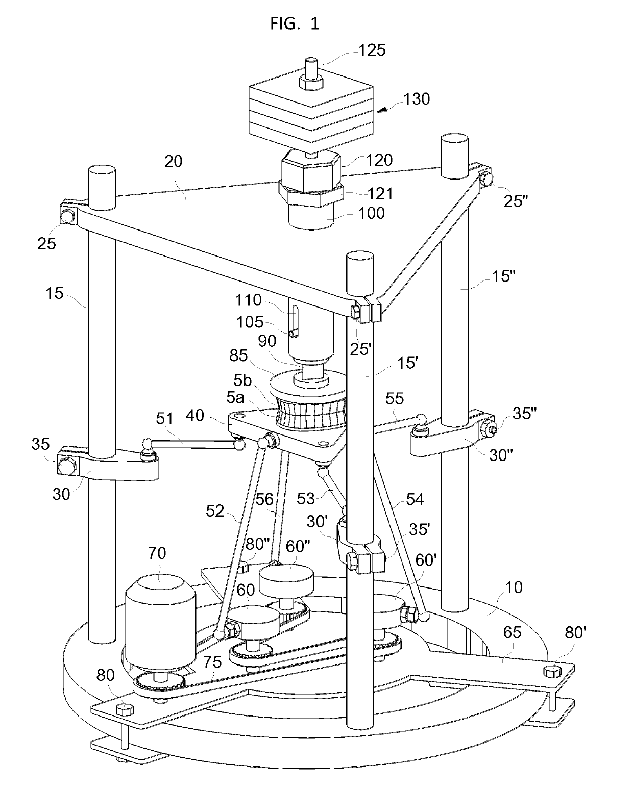
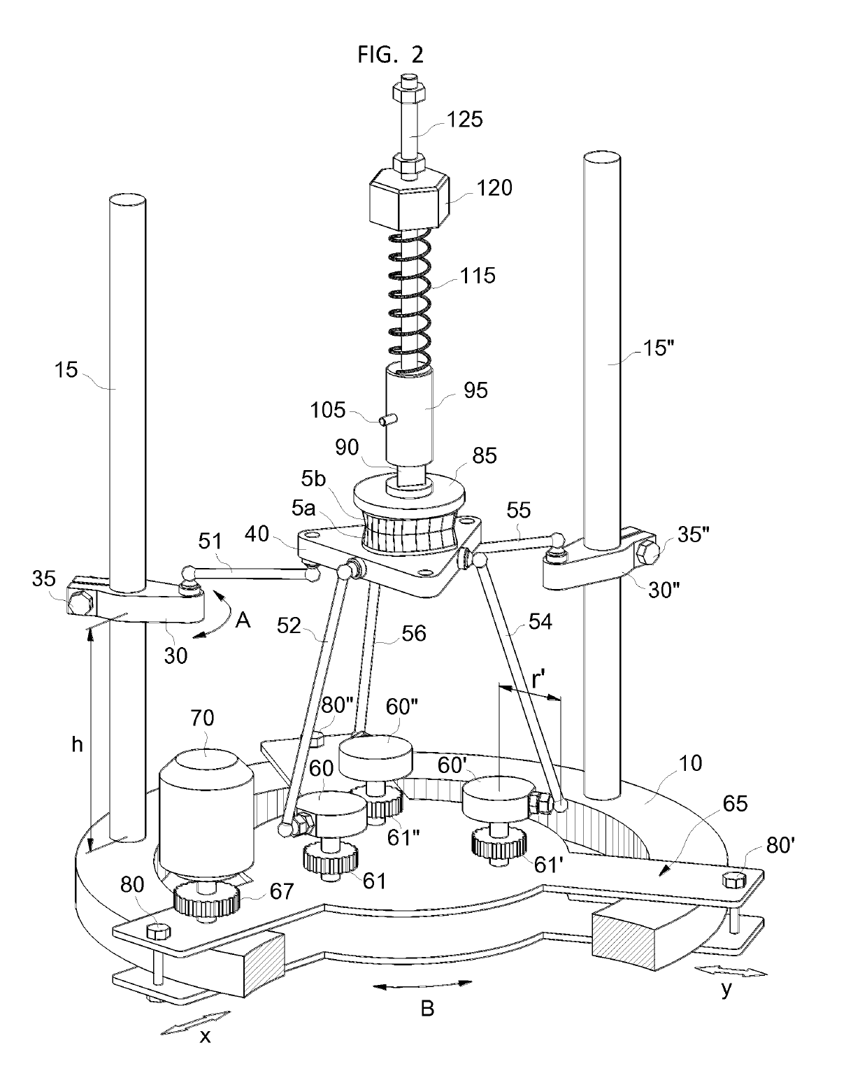
[0028]With reference to FIGS. 1 and 2, parallel mechanism masticator and chewing apparatus (apparatus) of the present invention includes a ring-shaped base 10 upon which three columns 15, 15′ and 15″ are attached. The upper ends of said columns are stiffened together by a top plate 20, the height of which can be adjusted by the means of screws 25, 25′ and 25″.
[0029]Apparatus also includes brackets 30, 30′ and 30″ mounted each along columns 15, 15′ and 15″, the elevation h, h′ and h″ (h′ and h″ not shown) and angular orientation A, A′ and A″ (A′ and A″ not shown) of said brackets being adjustable by the means of screws 35, 35′ and 35″.
[0030]Apparatus further includes a moving platform 40 which is supported by six ball-jointed rods 51, 52, 53, 54, 55 and 56, of which 51, 53 and 55 are passive rods and 52, 54 and 56 are driving rods.
[0031]Apparatus also includes rotary cranks 60, 60′ and 60″ mounted on a carrier 65 which is clamped onto the ring-shaped base 10 at positions x and y, and...
PUM
Abstract
The present invention is concerned with an apparatus for simulating the chewing process for the purpose of testing dental materials and implants and for the purpose of analyzing food samples. The apparatus comprises a frame, a stationary platform connected compliantly to the said frame and a moving platform corresponding to the maxillae and mandible of humans or animals, to which dentures or teeth are affixed. The moving platform is guided and driven in mandibular motion using six rods fitted with spherical joints at both ends. Said ball-jointed rods are attached with one end to the moving platform, and with the other end either to the frame of the apparatus, or to rotary cranks driven synchronously by a motor via a transmission. The rotary cranks together with their motor and transmission are mounted on a carrier which is adjustably attached to the frame of the apparatus. To closely reproduce a desired mandibular motion, the locations of the spherical joints to the frame, the position and orientation of the carrier relative to the frame, and the lengths of the rotary cranks and of the ball-jointed rods are suitably adjusted.
Description
BACKGROUND—PRIOR ART[0001]The following is a tabulation of some prior art that presently appears relevantNumberKind CodeIssue DatePatentee4,330,276May 18, 1982Becker et al.4,351,553Sep. 28, 1982Rovetta et al.4,468,198Aug. 28, 1984Kataolka et a1.4,976,582Dec. 11, 1990Clavel5,006,065Apr. 9, 1991Waysenson5,055,041Oct. 8, 1991Eckland5,699,695Dec. 23, 1997Canfeld et al.5,743,732Apr. 28, 1998Watson5,771,747Jun. 30, 1998Sheldon5,865,063Feb. 2, 1999Sheldon5,893,296Apr. 13, 1999Rosheim6,120,290Sep. 19, 2000Fukushima et al.6,196,081B1Mar. 6, 2001Yau6,503,033B1Jan. 7, 2003Kim et al.6,547,172B2Apr. 15, 2003Reinders et al.7,124,660B2Oct. 24, 2006Chiang7,172,385B2Feb. 6, 2007Khajepour et al.7,204,168B2Apr. 17, 2007Najafi et al.7,472,622B2Jan. 6, 2009Isobe et al.7,686,529B1Mar. 30, 2010Le et al.7,881,823B2Feb. 1, 2011Demathelin et al.8,021,149B2Sep. 20, 2011Gutman et al.8,151,660B2Apr. 10, 2012Wood8,333,766B2Dec. 18, 2012Edelhauser et al.8,442,677B2May 14, 2013ShohamNONPATENT LITERATURE DOCUMENTS[...
Claims
Application Information
Patent Timeline
Application Date:The date an application was filed.
Publication Date:The date a patent or application was officially published.
First Publication Date:The earliest publication date of a patent with the same application number.
Issue Date:Publication date of the patent grant document.
PCT Entry Date:The Entry date of PCT National Phase.
Estimated Expiry Date:The statutory expiry date of a patent right according to the Patent Law, and it is the longest term of protection that the patent right can achieve without the termination of the patent right due to other reasons(Term extension factor has been taken into account ).
Invalid Date:Actual expiry date is based on effective date or publication date of legal transaction data of invalid patent.

