Synchronizer and method for shifting a gear

Active Publication Date: 2019-04-25
HOERBIGER ANTRIEBSTECHN HLDG
View PDF0 Cites 0 Cited by
  • Summary
  • Abstract
  • Description
  • Claims
  • Application Information

AI Technical Summary

Benefits of technology

[0023]In particular, the exerted axial force is greater than the frictional force between the thrust piece and the synchronizer body. Due to this force ratio, the axial compressive force exerted by t

Problems solved by technology

The disadvantage consists in that when engaging a gear, an increased expenditure of force is necessary in order to overcome the fric

Method used


Image

  • Synchronizer and method for shifting a gear
  • Synchronizer and method for shifting a gear
  • Synchronizer and method for shifting a gear

Examples


Embodiment Construction

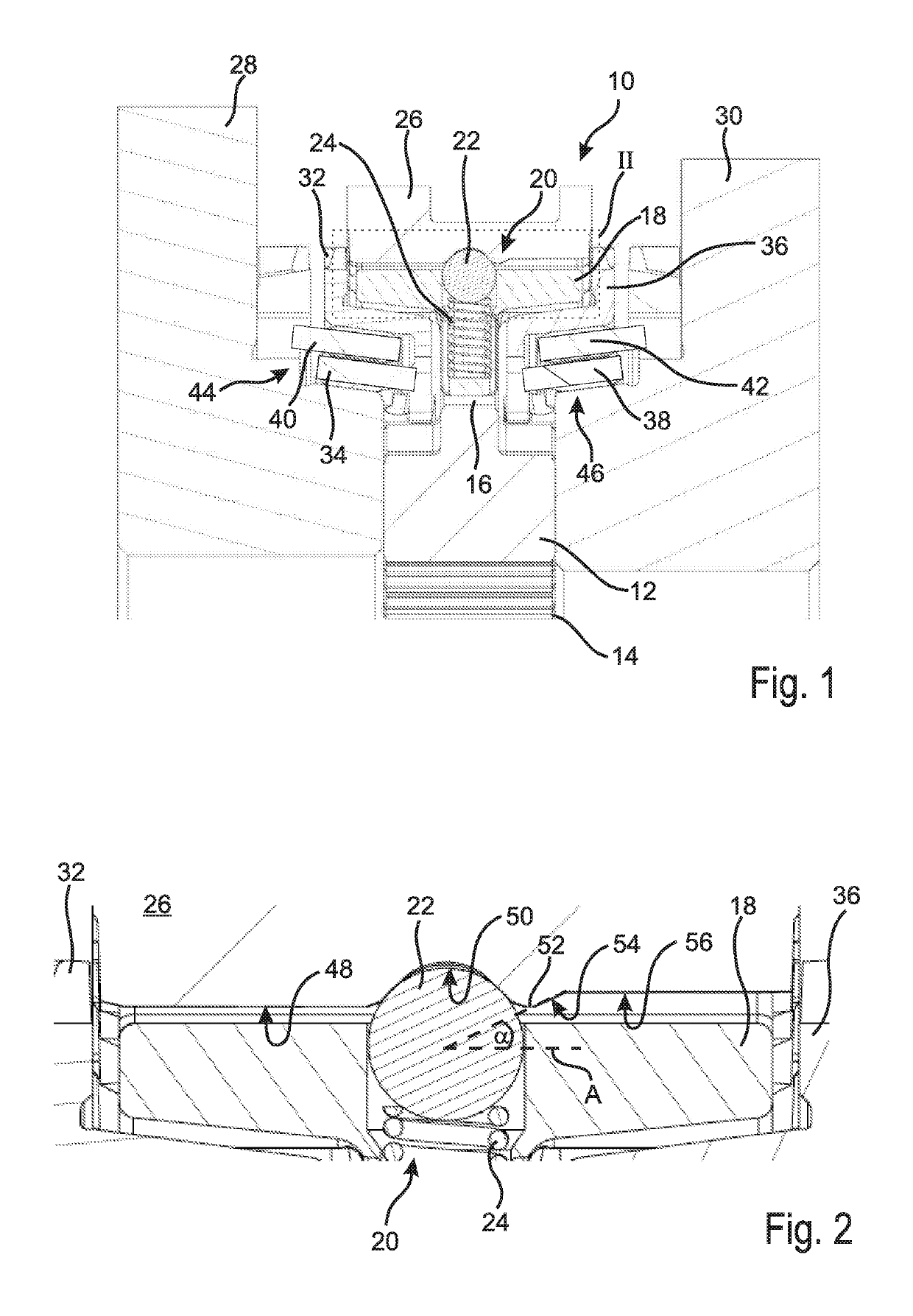
[0033]FIG. 1 shows a synchronizer 10 which includes a synchronizer body 12 which via a toothing 14 is non-rotatably arranged on a non-illustrated transmission shaft. The transmission shaft rotates about an axis which in FIG. 1 lies horizontally below the toothing 14.

[0034]The synchronizer body 12 includes a hub portion 16 in which a thrust piece 18 is shiftably arranged. To the thrust piece 18 an actuating element 20 is associated, which in the embodiment shown is formed by a ball 22 and a spring 24. The spring 24 supports on the thrust piece 18 and urges the ball 22 in direction of a sliding sleeve 26, i.e. radially to the outside.

[0035]The sliding sleeve 26 is non-rotatably connected with the synchronizer body 12 and can axially be shifted in opposite directions in order to couple the synchronizer body 12 with a first transmission gear 28 or a second transmission gear 30, whereby a torque can be transmitted from the transmission shaft to the corresponding transmission gear 28, 30....


PUM


Abstract

A method for shifting a gear in a synchronizer comprising a synchronizer body arranged on a transmission shaft, a first and a second synchronizer associated to a first and a second transmission gear, wherein the synchronizer has a sliding sleeve and at least one thrust piece which is shiftably arranged on the synchronizer body and can exert an axial compressive force on the corresponding synchronizer ring. The synchronizer includes an elastic actuating element active between the sliding sleeve and the thrust piece, and the sliding sleeve has a detent recess for the neutral position and a release contour that can cooperate with the actuating element such that when the sliding sleeve is shifted for being engaged with one of the transmission gears, the thrust piece is urged away from the corresponding synchronizer ring.

Description

[0001]This invention relates to a synchronizer for a gear transmission and to a method for shifting a gear in a synchronizer.BACKGROUND OF THE INVENTION[0002]From the prior art synchronizers are known, which include a synchronizer body associated to a transmission shaft. On the synchronizer body a thrust piece typically is shiftably arranged, which during a shifting operation is moved by a sliding sleeve such that it activates a synchronizer ring. The synchronizer ring in turn cooperates with a transmission gear, whereby the rotational speeds of the synchronizer body and of the corresponding transmission gear can be synchronized. After synchronization of the rotational speeds, the sliding sleeve is shifted further so that a torque can be transmitted from the synchronizer body arranged on the transmission shaft to the corresponding transmission gear.[0003]It was found that on meshing of the sliding sleeve on the transmission gear, the synchronizer ring continues to be axially loaded ...

Claims


Application Information

Patent Timeline
IPC IPC(8): F16D23/06F16H63/30
CPCF16D23/06F16H63/30F16H2063/3093F16D2023/0631F16D2023/0618
Inventor BACK, OTTMAR
Owner HOERBIGER ANTRIEBSTECHN HLDG
Why Eureka
Try Eureka