Panoramic reconstruction of temporal imaging

a temporal image and panoramic reconstruction technology, applied in the field of temporal imaging, can solve the problems of affecting the application of temporal imaging systems to the study, affecting the accuracy of temporal imaging, and significant challenges in experimental real-time observation

Active Publication Date: 2019-04-25
THE UNIVERSITY OF HONG KONG
View PDF0 Cites 11 Cited by
  • Summary
  • Abstract
  • Description
  • Claims
  • Application Information

AI Technical Summary

Benefits of technology

[0008]The present invention is directed to an ultrafast single-shot waveform characterization system and approach that enable scalable temporal record-length and sub-ps temporal resolution simultaneously, thus breaking through the limitation of time-bandwidth product (“TBWP”) in traditional single-shot waveform measurement techniques.

Problems solved by technology

On the other hand, just like there are always limitations on the field-of-view in any spatial imaging system, the single-shot record length ΔT or the temporal aperture of temporal imaging systems has previously been limited to less than 300 ps [18].
Such a situation hinders the applications of temporal imaging systems to the study of many important optical nonlinear dynamic phenomena, where not only fine temporal details but also long evolution information are necessary for a comprehensive understanding of the phenomena.
While the soliton generation benefits greatly from the ultrahigh quality factor (Q) of the microresonator, the ultrahigh Q also renders its formation and transition dynamics slowly evolved at a time scale much longer than the cavity roundtrip time [24, 25], which causes significant challenges in the experimental real-time observation.
Meanwhile, limitations on TBWP also exist for other techniques that achieve comparable performance [28-32].
Even though a TBWP larger than 320,000 has been demonstrated at a 160-GHz detection bandwidth, it is practically challenging to scale the detection bandwidth beyond 1 THz (i.e., sub-ps temporal resolution).

Method used


Image

  • Panoramic reconstruction of temporal imaging
  • Panoramic reconstruction of temporal imaging
  • Panoramic reconstruction of temporal imaging

Examples


Embodiment Construction

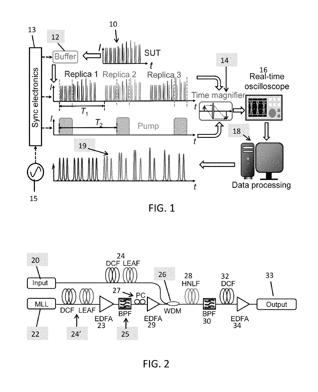
[0021]FIG. 1 shows how the PARTI system overcomes the limitation of TBWP in conventional temporal imaging systems and thus captures slowly-evolved soliton dynamics. The signal under test (SUT) 10 is an exemplary pulse train. Since the SUT is transient and non-repetitive, the concept of image stitching in the spatial domain cannot be conveniently adopted in temporal imaging systems. To address this problem, a fiber-loop based optical buffer 12 is integrated with a time magnifier 14 to realize temporal scanning using stroboscopic signal acquisition, a technique commonly adopted in sampling oscilloscopes. As shown in FIG. 1, the optical buffer 12 in the PARTI system creates multiple identical replicas of the signal under test with a constant time interval. These replicas will be subsequently measured by the time magnifier 14 that follows the buffer. Thus the temporal scanning on a transient SUT is realized.

[0022]Using the optical buffer 12, the SUT replicas can be generated with a pre-...


PUM


Abstract

The panoramic-reconstruction temporal imaging (PARTI) system is a single-shot optical waveform measurement apparatus that achieves scalable record length and sub-picosecond resolution simultaneously for ultrafast non-repetitive waveform characterization, in analogy with the wisdom of stitching multiple mosaic images to achieve larger-field-of-view in the spatial domain. It consists of a high-fidelity optical buffer, a low-aberration time magnifier and synchronization-control electronics. For specific measurement circumstances, the PARTI system can also be carried out based on a passive optical buffer, which reduces the system complexity. The PARTI system is configured for real-time single-shot characterization of non-repetitive optical dynamic waveform that evolves over a time scale much larger than that of its ultrafast temporal details, i.e., optical dynamics with large time-bandwidth product.

Description

TECHNICAL FIELD[0001]The present invention is generally directed to temporal imaging, and more particularly to the panoramic reconstruction of temporal images.BACKGROUND OF THE INVENTION[0002]The ability to characterize arbitrary and non-repetitive optical waveforms with sub-picosecond (sub-ps) resolution in single-shot and in real-time is beneficial in different fields, such as advanced optical communication [1, 2], ultrashort pulses generation [3, 4], optical devices evaluation [5] and ultrafast bio-imaging [6, 7]. The references identified in square brackets are listed below and are incorporated herein by reference in their entirety.[0003]More importantly, it has helped reveal fascinating ultrafast phenomena in optics, such as the onset of mode-locking [8, 9], soliton explosions [10-11] and optical rogue waves [12-14. Temporal imaging system is one of the most promising techniques perceived and developed to meet the needs of single-shot, real-time waveform characterization [15-17...

Claims


Application Information

Patent Timeline
Patent Type & Authority Applications(United States)
IPC IPC(8): G01J11/00G01J9/00
CPCG01J11/00G01J9/00G02B6/2861H01S3/06754
Inventor WONG, KENNETH KIN YIPLI, BOWEN
Owner THE UNIVERSITY OF HONG KONG
Why Eureka
Try Eureka