
Real-time location system (RTLS) having tags, beacons and bridges, that uses a combination of motion detection and RSSI measurements to determine room-location of the tags

a real-time location and tag technology, applied in the field of real-time location systems, can solve problems such as insufficient patient and staff tags for some hospital use cases, inability to provide highly accurate results, and misplaced room estimates

Active Publication Date: 2019-04-25
INFINITE LEAP
View PDF9 Cites 16 Cited by
  • Summary
  • Abstract
  • Description
  • Claims
  • Application Information

AI Technical Summary

Benefits of technology

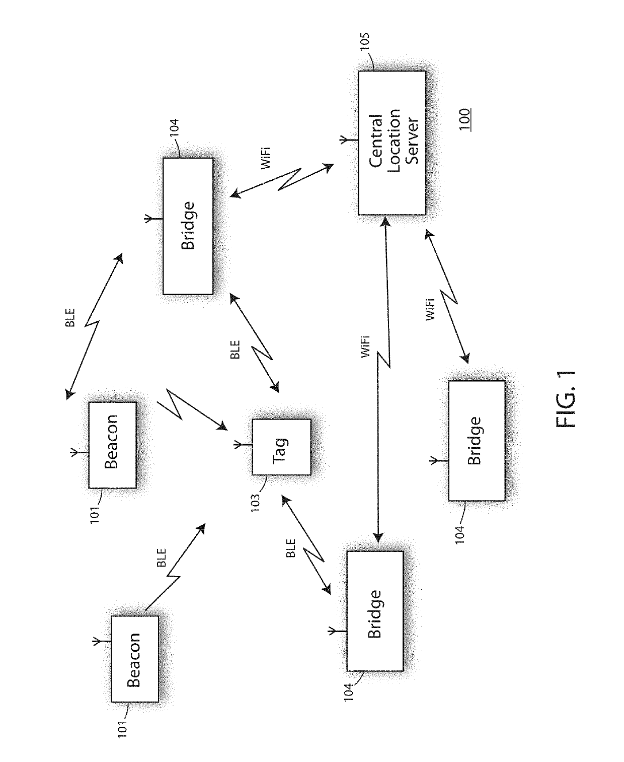
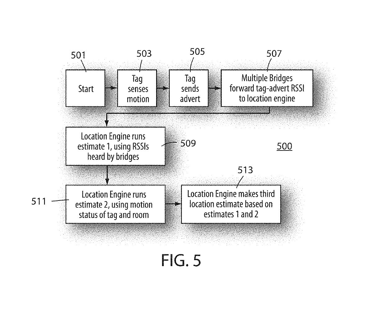
The present invention relates to a real-time location system (RTLS) that uses active tags with motion sensors and radio signals to determine the location of assets, such as equipment and patients, in indoor environments like hospitals. The invention aims to provide a more accurate and reliable location fix for these assets, as current RTLS systems based on multi-lateration algorithms alone are not sufficient for all use cases. The invention combines the use of motion sensors, radio signals, and location information from fixed receivers to estimate the location of tags in real-time. The invention can also use the advertisements of tags to locate assets in adjacent rooms, which is important in environments like hospitals where assets are often stored in multiple rooms and need to be quickly located. Overall, the invention provides a better solution for accurately tracking and locating assets in indoor environments.

Problems solved by technology

But they fail to provide a highly accurate, room-level location fix for the environments that need to estimate which room an asset resides in, like hospitals.
These current systems and methods of locating asset, patient and staff tags are insufficient for some hospital use cases.
The challenge of the RTLS system is to locate each piece of equipment and reliably tell the nurses which equipment is in the clean room (so it can be used) versus which equipment is in the soiled room (which cannot be used on a patient until it is cleaned and moved to the clean room).
It may be able to locate each tag to within one meter of its true location, but it cannot tell whether the asset is one-half meter to the left of the wall, or one-half meter to the right of the wall, so it misplaces the room estimate for some assets.

Method used


Image

  • Real-time location system (RTLS) having tags, beacons and bridges, that uses a combination of motion detection and RSSI measurements to determine room-location of the tags
  • Real-time location system (RTLS) having tags, beacons and bridges, that uses a combination of motion detection and RSSI measurements to determine room-location of the tags
  • Real-time location system (RTLS) having tags, beacons and bridges, that uses a combination of motion detection and RSSI measurements to determine room-location of the tags

Examples


Embodiment Construction

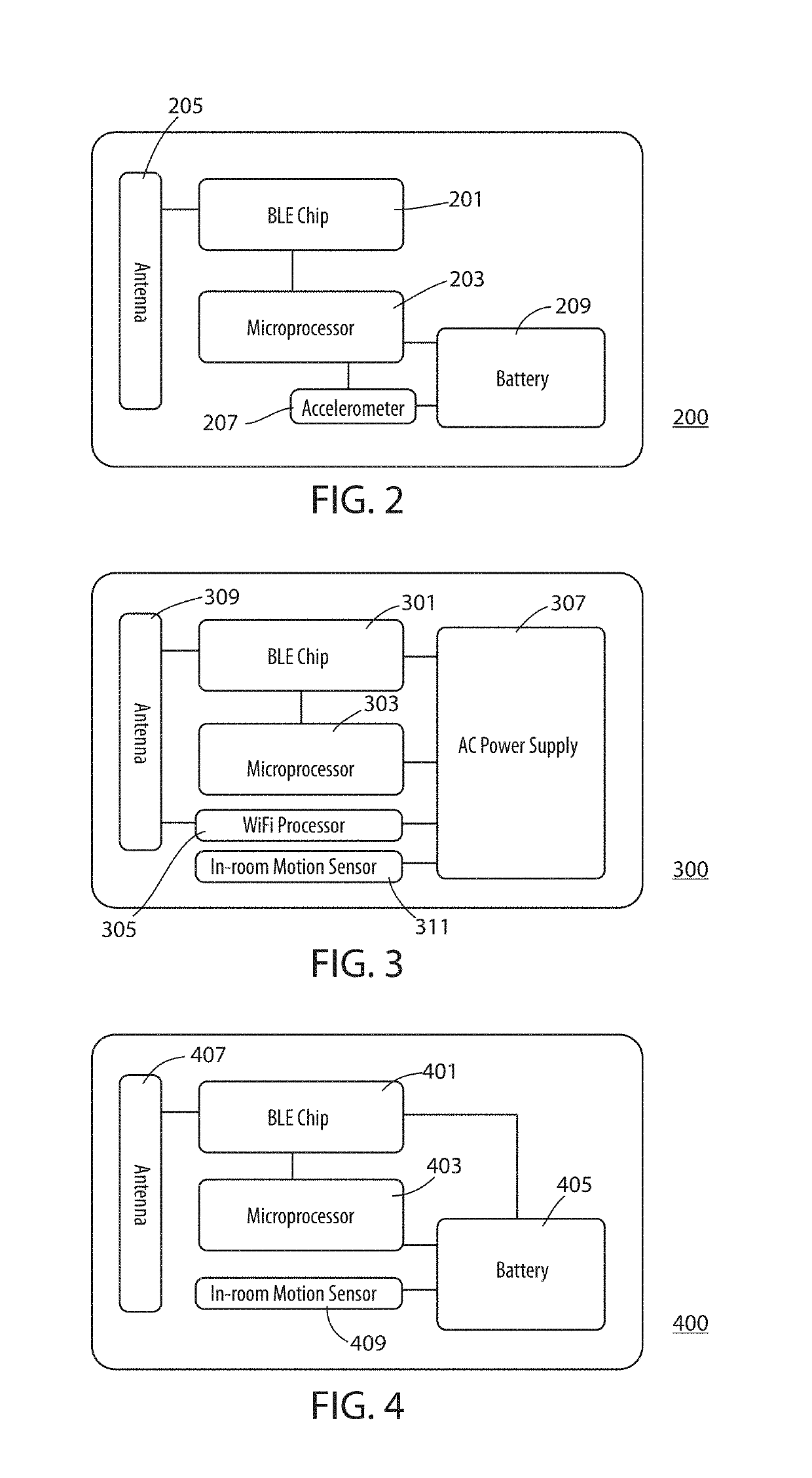
[0015]Before describing in detail embodiments that are in accordance with the present invention, it should be observed that the embodiments reside primarily in combinations of method steps and apparatus components related to an RTLS having stationary beacons that advertise, active tags that transmit advertisements, and bridges that pass beacon and tag information to a location algorithm in a central server. Accordingly, the apparatus components and method steps have been represented where appropriate by conventional symbols in the drawings, showing only those specific details that are pertinent to understanding the embodiments of the present invention so as not to obscure the disclosure with details that will be readily apparent to those of ordinary skill in the art having the benefit of the description herein.

[0016]In this document, relational terms such as first and second, top and bottom, and the like may be used solely to distinguish one entity or action from another entity or a...


PUM


Abstract

A real-time location system (RTLS) uses transmitting and listening tags, bridges, and beacons. The fixed beacons broadcast BLE advertisements containing motion-status information about recent history of perceived motion in. a room as determined from a motion sensor in the beacon. The bridges forward the beacon's received advertisements to a location engine, which records timestamps of motion events seen by each beacon in each room. One or more tags then report their own motion status based on a tag-based accelerometer. The system utilizes a series of location-engine steps, to estimate the room-location of the tags based on a specific combination of RSSI analysis, and a comparison of tag-motion history to the perceived arid recorded motion-status in a room. This analysis of tag-motion history and motion-in-room status produces a better estimate of room-level location of the tag than can be estimated by simple proximity or multi-lateration using radio signal strengths.

Description

FIELD OF THE INVENTION[0001]The present invention relates generally to a real-time location system (RTLS) having active tags that transmit BLE advertisements, and bridges that pass tag-location information to a location algorithm in a central server. The method defined uses a combination of motion sensors, motion detectors, and radio signal strength to determine what room a tag is located in.BACKGROUND OF THE INVENTION[0002]RTLS systems estimate locations for moving tags within a floor plan of interior rooms, in buildings such as hospitals. Many existing RTLS systems based on radio-frequency signals such as Wi-Fi or BLE, are designed to have moving tags that transmit a radio message, in a field of receiving devices called gateways, sensors, bridges, or Access Points. The network of gateways will use received signal strength of radio transmissions from a tag, as a proxy for estimating the distance between the tag and each gateway and use proximity or multi-lateration algorithms to es...

Claims


Application Information

Patent Timeline
Patent Type & Authority Applications(United States)
IPC IPC(8): H04W4/029H04W4/02H04W4/80H04W4/33
CPCH04W4/029H04W4/027H04W4/80H04W4/33H04W4/02H04W4/90G01S5/0036G01S5/14H04W8/005G08B13/2462H04W84/18H04L67/52G01S2205/01
Inventor SWART, JOHN A.
Owner INFINITE LEAP
Learn More