Rotary connector apparatus
a technology of rotary connectors and connectors, which is applied in the direction of flexible/turnable line connectors, emergency protective arrangements for limiting excess voltage/current, and coupling device connections, etc., can solve the problems of led circuit damage, flat cables, and the like, and the difficulty of replacing the connection components, so as to prevent electrical circuit damage resulting from inflow of overcurrent and replace the connection components easily
- Summary
- Abstract
- Description
- Claims
- Application Information
AI Technical Summary
Benefits of technology
Problems solved by technology
Method used
Image
Examples
embodiment 1
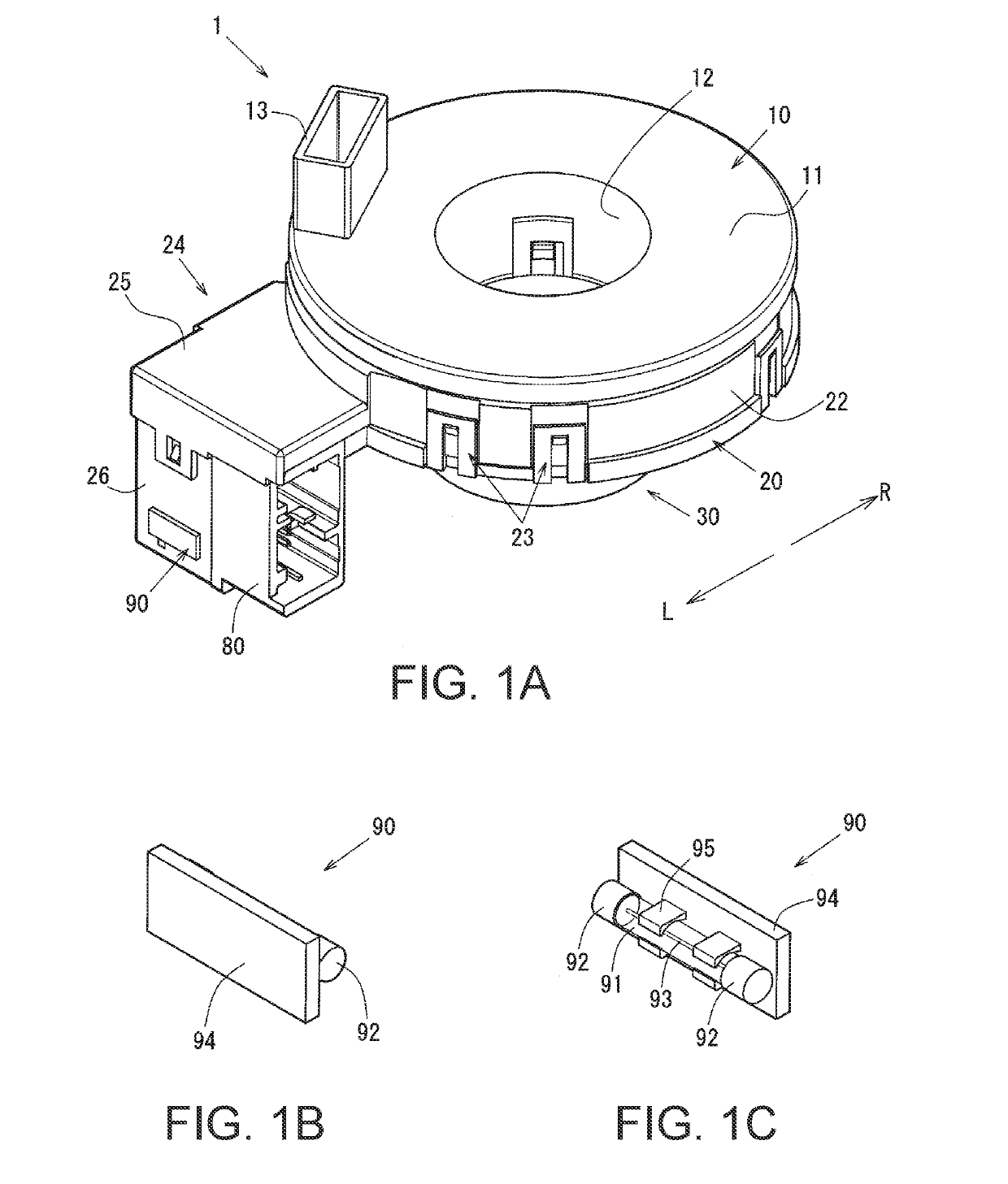
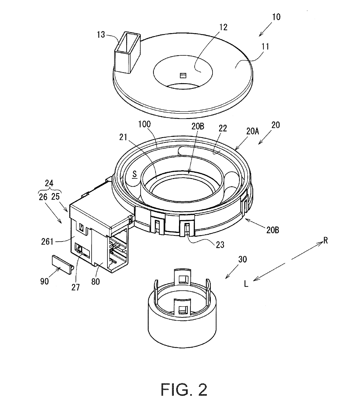
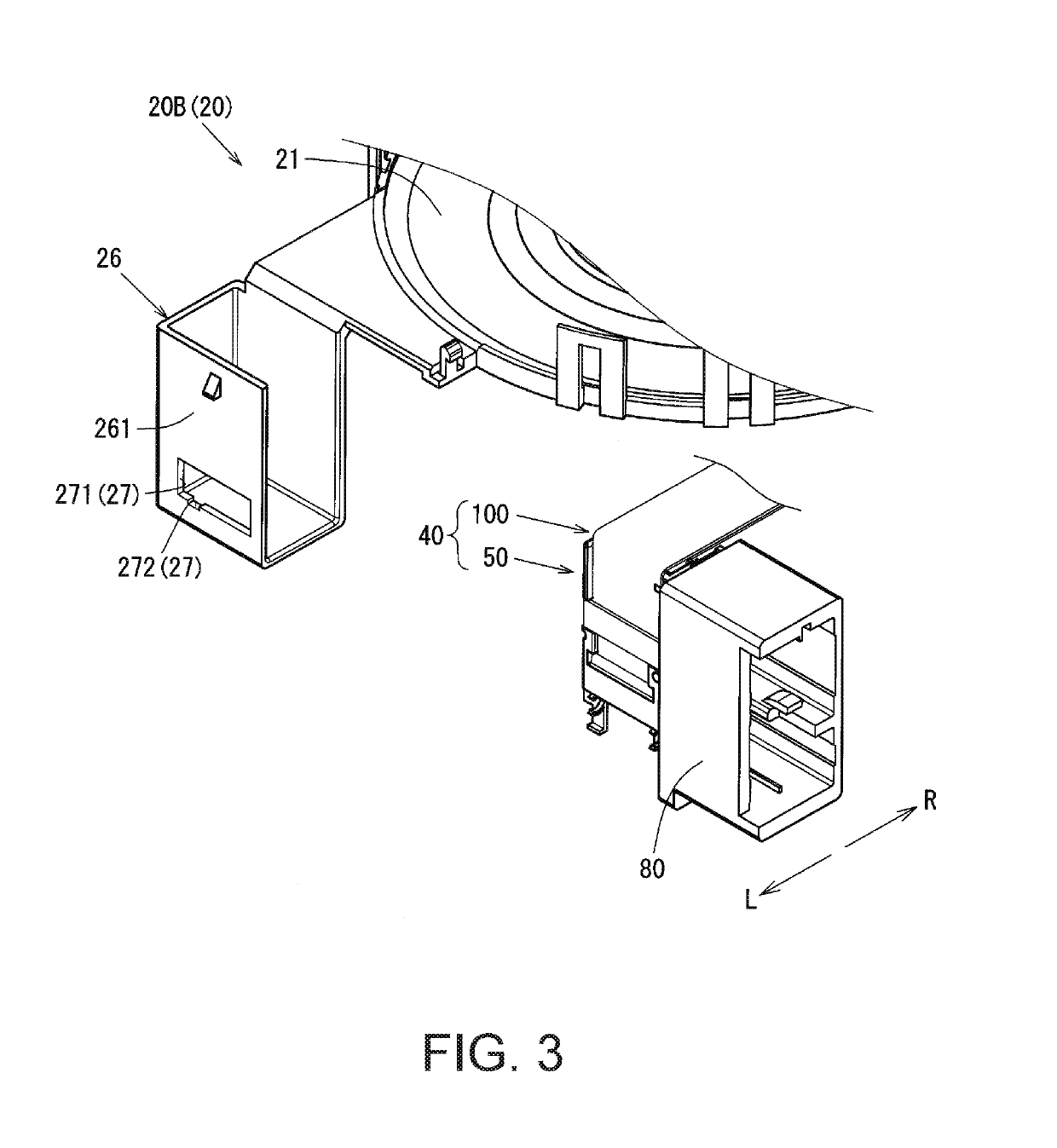
[0063]Next, a rotary connector apparatus 1 will be described with reference to FIGS. 1 to 7.
[0064]FIGS. 1A to 1C are perspective views schematically illustrating the rotary connector apparatus 1 and a fuse 90. More specifically, FIG. 1A is a perspective view schematically illustrating the rotary connector apparatus 1, and FIGS. 1B and 1C are enlarged perspective views schematically illustrating the fuse 90 (to be installed in a connection connector 50) as viewed from the upper right and upper left directions, respectively. Note that in the present embodiment, the side on which a rotator 10 is arranged relative to a stator 20 is the up direction, and the side on which a sleeve 30 is arranged is the down direction. Moreover, in FIGS. 1A through 1C, the near right side is the front direction and the far left side is the rear direction, while the near left side is the left direction L and the far right side is the right direction R.
[0065]FIG. 2 is an exploded perspective view schematica...
embodiment 2
[0155]Although in the embodiment described above the through-window 271 and the inspection window 272 are integrally formed (continuously connected), the through-window 271 and the inspection window 272 do not necessarily have to be integrally formed. As illustrated in FIG. 8A, for example, the through-window 271 and the inspection window 272 may be formed separately.
[0156]Next, a rotary connector apparatus 1a in which the through-window 271 and the inspection window 272 are formed separately will be briefly described.
[0157]Note that components in the rotary connector apparatus 1a that are the same as in the rotary connector apparatus 1 described above will be given the same reference characters as above and will not be described again here.
[0158]FIGS. 8A and 8B are explanatory drawings of a stator-side connector housing 24a which houses a connection connector-equipped flat cable 40. More specifically, FIG. 8A is a side view illustrating the stator-side connector housing 24a as view...
embodiment 3
[0168]More specifically, although in the rotary connector apparatus 1 the connection component is the fuse 90 configured as illustrated in FIGS. 1B and 1C, the connection component may be a so-called blade fuse 90b such as that illustrated in FIG. 9.
[0169]In this case, the shape of the component installation portions 76 that lock in the blade fuse 90b is changed to accommodate the blade fuse 90b.
[0170]Next, a rotary connector apparatus 1b in which the connection component is such a blade fuse 90b will be briefly described with reference to FIGS. 9 and 10.
[0171]Note that components in the rotary connector apparatus 1b described below that are the same as in the rotary connector apparatus 1 in the embodiment described above will be given the same reference characters as above and will not be described again here.
[0172]FIG. 9 includes a perspective view schematically illustrating a connector housing body 26 in a state in which the blade fuse 90b is not installed in a connection connec...
PUM
 Abstract
Description
Claims
Application Information
 - R&D
- Intellectual Property
- Life Sciences
- Materials
- Tech Scout
- Unparalleled Data Quality
- Higher Quality Content
- 60% Fewer Hallucinations
Browse by: Latest US Patents, China's latest patents, Technical Efficacy Thesaurus, Application Domain, Technology Topic, Popular Technical Reports.
© 2025 PatSnap. All rights reserved.Legal|Privacy policy|Modern Slavery Act Transparency Statement|Sitemap|About US| Contact US: help@patsnap.com


