Polarizing plate, and liquid crystal display comprising same

Active Publication Date: 2019-03-28
LG CHEM LTD
View PDF6 Cites 1 Cited by
  • Summary
  • Abstract
  • Description
  • Claims
  • Application Information

AI Technical Summary

Benefits of technology

[0013]A polarizing plate according to one embodiment of the present application is capable of preventing circuit damages caused by static electricity generated when peeling off a protective film since a photocurable resin layer has low sheet resistance and the protective film has an antistatic function leading to a low peeling static voltage.
[0014]In addition, a polarizing plate according to one embodiment of the present application has peel strength effective for interfacial adhesion with a protective film while readily peeling off the protective film, and therefore, excellent processi

Problems solved by technology

As a polarizer used in the polarizing plate, a uniaxially extended PVA-based film dyed with iodine is much used, and since it is thin and has poor strength, a protective film is required.
However, a TAC film, a polarizer protective film that has been normally used in the art, does not have favorable moisture-heat resistance, and has weak pencil hardness and scratch resistance properties, and separate hard coating is required.
Displays become thinner and larger nowadays, and accordingly, a gap between a lower pol and a BLU decreases and lower polarizing plate sagging occurs causing a branching phenomenon of the protective

Method used


Image

  • Polarizing plate, and liquid crystal display comprising same

Examples


Example

EXAMPLE 1

[0098]A coating solution was prepared by mixing 50 g of trimethylolpropane triacrylate (TMPTA), 20 g of DPCA120 (Nippon Kayaku, caprolactone-modified hexafunctional acrylate), 30 g of 9-ethylene glycol diacrylate (9-EGDA), 5 g of an ionic compound FC4400 (3M), 1 g of a photopolymerization initiator (product name Darocur TPO) and 100 g of ethanol, and, in order to provide an antistatic function, the coating solution was bar coated on a PET film, a protective film provided with an antistatic surface. This was dried for 2 minutes at 60° C., and then irradiated with D-bulb UV (200 mJ / cm2) under nitrogen atmosphere to obtain a photocurable resin layer having a thickness of 10 μm.

Example

EXAMPLE 2

[0099]A coating solution was prepared by mixing 50 g of pentaerythritol tri(tetra)acrylate, 50 g of 9-ethylene glycol diacrylate (9-EGDA), 5 g of an ionic compound FC4400 (3M) and 1 g of a photopolymerization initiator (product name Darocur TPO), and, in order to provide an antistatic function, the coating solution was bar coated on a 38 μm PET film, a protective film provided with an antistatic surface. This was irradiated with D-bulb UV (200 mJ / cm2) under nitrogen atmosphere to obtain a photocurable resin layer having a thickness of 10 μm.

Example

EXAMPLE 3

[0100]A coating solution was prepared by mixing 50 g of trimethylolpropane triacrylate (TMPTA), 50 g of TA604AU (NOF Corporation, ethylene oxide-modified trifunctional acrylate), 5 g of an ionic compound FC4400 (3M), 1 g of a photopolymerization initiator (product name Darocur TPO) and 100 g of ethanol, and, in order to provide an antistatic function, the coating solution was bar coated on a 38 μm PET film, a protective film provided with an antistatic surface. This was dried for 2 minutes at 60° C., and then irradiated with D-bulb UV (200 mJ / cm2) under nitrogen atmosphere to obtain a photocurable resin layer having a thickness of 10 μm.


PUM

PropertyMeasurementUnit
Fractionaaaaaaaaaa
Fractionaaaaaaaaaa
Fractionaaaaaaaaaa

Abstract

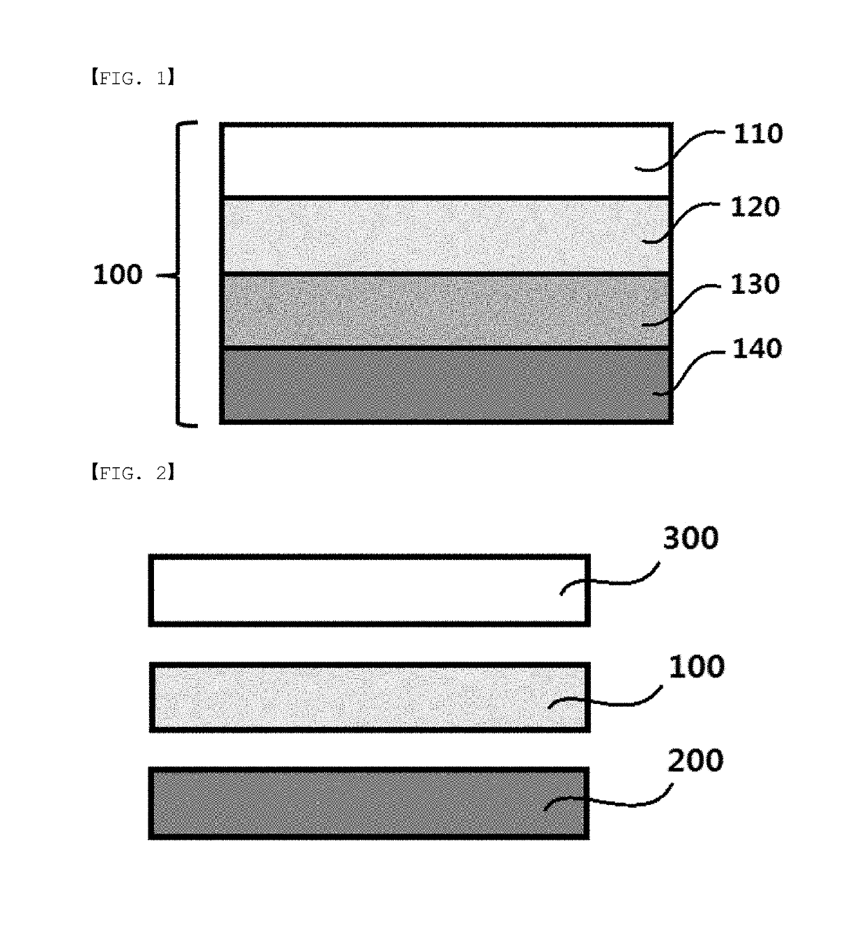
The present application relates to a polarizing plate and a liquid crystal display comprising same, the polarizing plate comprising: a base film; an adhesive layer provided on one side of the base film; a photocurable resin layer provided on one side of the adhesive layer; and a protective film provided on one side of the photocurable resin layer, wherein the photocurable resin layer comprises: a cured resin having a polyfunctional acrylate-based monomer, and an acrylic elastic polymer or an acrylate-based oligomer having an elongation of 5-200%; a photopolymerization initiator; and an antistatic agent, and the protective film is provided with an antistatic surface on one side thereof, which is opposite to the other side facing the photocurable resin layer.

Description

TECHNICAL FIELD[0001]The present specification claims priority to and the benefits of Korean Patent Application No. 10-2016-0054218, filed with the Korean Intellectual Property Office on May 2, 2016, and Korean Patent Application No. 10-2016-0054216, filed with the Korean Intellectual Property Office on May 2, 2016, the entire contents of which are incorporated herein by reference.[0002]The present application relates to a polarizing plate and a liquid crystal display device including the same.BACKGROUND ART[0003]A polarizing plate is useful as an optical component forming a liquid crystal display device. As a polarizing plate in the art, those having a constitution of laminating a protective layer including a transparent resin film on one surface or both surfaces of a polarizing film using an aqueous adhesive and the like have been used.[0004]As such a transparent resin film, a triacetyl cellulose film (TAC film) has been much used due to its excellent optical transparency or moist...

Claims


Application Information

Patent Timeline
IPC IPC(8): G02F1/1335G02B1/14G02B5/30B32B27/30
CPCG02B5/3033G02B1/14B32B27/30G02F1/133528G02F1/133602G02B1/16G02F2202/22G02F2202/28B32B7/12B32B27/18B32B27/308C09K3/16G02B5/3041G03F7/004G03F7/027G03F7/028B32B2307/21C09K2323/035C09K2323/057
Inventor LEE, HANNAKIM, HYE MINSON, HYUN SAMHONG, KYUNGKIJANG, YEONGRAE
Owner LG CHEM LTD
Why Eureka
Try Eureka