Rotary connector apparatus

a technology of rotary connectors and connectors, which is applied in the direction of flexible/turnable line connectors, emergency protective arrangements for limiting excess voltage/current, and coupling device connections, etc., can solve the problems of led circuit damage, flat cables, and the like, and the difficulty of replacing the connection components, so as to prevent electrical circuit damage resulting from inflow of overcurrent and replace the connection components easily

Active Publication Date: 2020-11-03
KOETTER RAX LLC +2
View PDF34 Cites 1 Cited by
  • Summary
  • Abstract
  • Description
  • Claims
  • Application Information

AI Technical Summary

Benefits of technology

[0010]In light of the foregoing problems, the present invention aims to provide a rotary connector apparatus including a connection connector-equipped flat cable, which makes it possible to prevent electrical circuit damage resulting from inflow of overcurrent and which also makes it possible to easily replace a connection component (protection device).

Problems solved by technology

However, inflow of extremely large currents (hereinafter, overcurrent) resulting from external noise or the like, for example, can potentially damage LED circuits, flat cable, and the like.
However, because this connection component is fixed to the busbars arranged between the conductor and the external conductor, it is extremely difficult to replace the connection component in cases such as when the connection component does break and interrupt the flow of current, for example.

Method used


Image

  • Rotary connector apparatus
  • Rotary connector apparatus
  • Rotary connector apparatus

Examples


embodiment 1

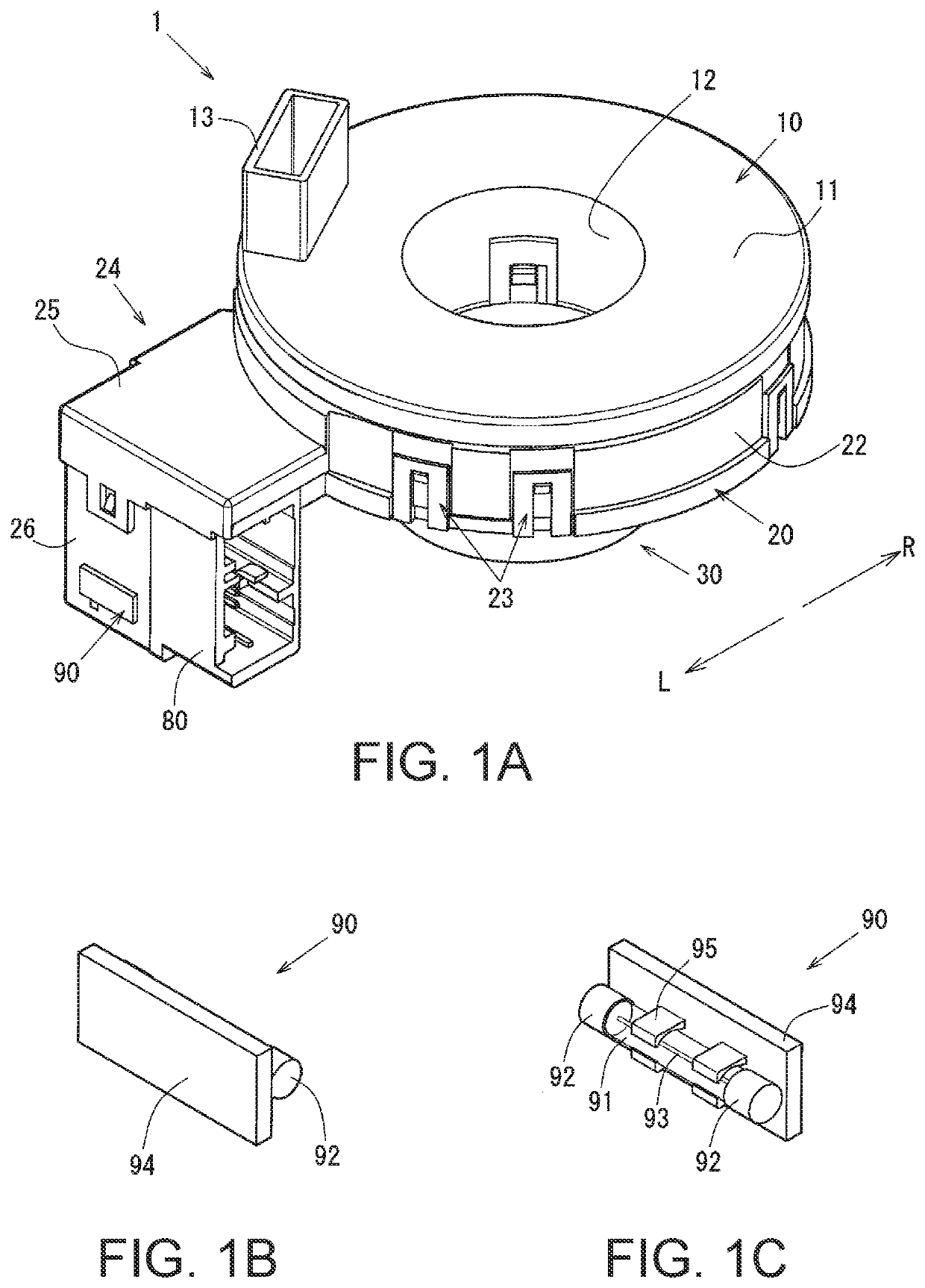
[0063]Next, a rotary connector apparatus 1 will be described with reference to FIGS. 1 to 7.

[0064]FIGS. 1A to 1C are perspective views schematically illustrating the rotary connector apparatus 1 and a fuse 90. More specifically, FIG. 1A is a perspective view schematically illustrating the rotary connector apparatus 1, and FIGS. 1B and 1C are enlarged perspective views schematically illustrating the fuse 90 (to be installed in a connection connector 50) as viewed from the upper right and upper left directions, respectively. Note that in the present embodiment, the side on which a rotator 10 is arranged relative to a stator 20 is the up direction, and the side on which a sleeve 30 is arranged is the down direction. Moreover, in FIGS. 1A through 1C, the near right side is the front direction and the far left side is the rear direction, while the near left side is the left direction L and the far right side is the right direction R.

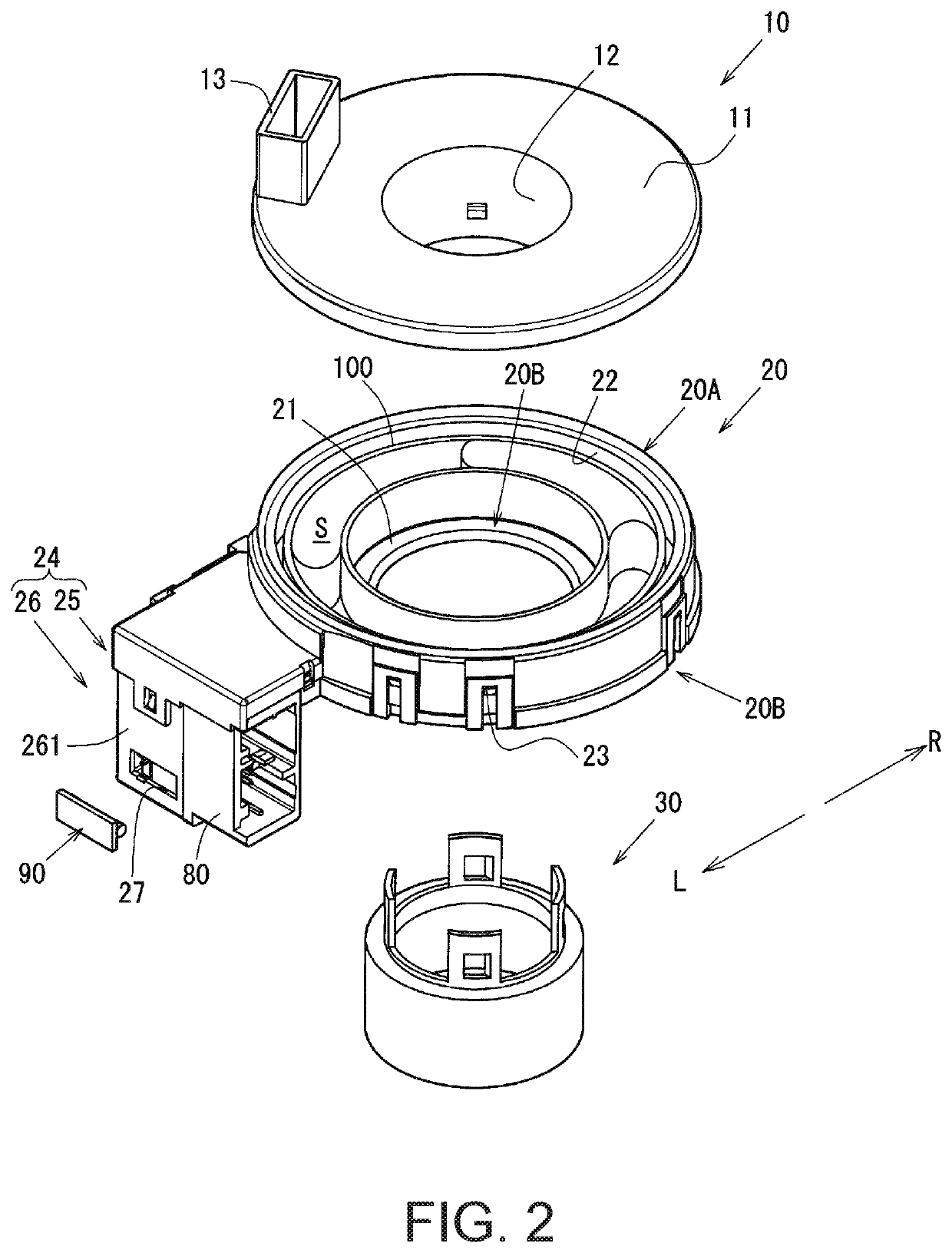
[0065]FIG. 2 is an exploded perspective view schematica...

embodiment 2

[0155]Although in the embodiment described above the through-window 271 and the inspection window 272 are integrally formed (continuously connected), the through-window 271 and the inspection window 272 do not necessarily have to be integrally formed. As illustrated in FIG. 8A, for example, the through-window 271 and the inspection window 272 may be formed separately.

[0156]Next, a rotary connector apparatus 1a in which the through-window 271 and the inspection window 272 are formed separately will be briefly described.

[0157]Note that components in the rotary connector apparatus 1a that are the same as in the rotary connector apparatus 1 described above will be given the same reference characters as above and will not be described again here.

[0158]FIGS. 8A and 8B are explanatory drawings of a stator-side connector housing 24a which houses a connection connector-equipped flat cable 40. More specifically, FIG. 8A is a side view illustrating the stator-side connector housing 24a as view...

embodiment 3

[0168]More specifically, although in the rotary connector apparatus 1 the connection component is the fuse 90 configured as illustrated in FIGS. 1B and 1C, the connection component may be a so-called blade fuse 90b such as that illustrated in FIG. 9.

[0169]In this case, the shape of the component installation portions 76 that lock in the blade fuse 90b is changed to accommodate the blade fuse 90b.

[0170]Next, a rotary connector apparatus 1b in which the connection component is such a blade fuse 90b will be briefly described with reference to FIGS. 9 and 10.

[0171]Note that components in the rotary connector apparatus 1b described below that are the same as in the rotary connector apparatus 1 in the embodiment described above will be given the same reference characters as above and will not be described again here.

[0172]FIG. 9 includes a perspective view schematically illustrating a connector housing body 26 in a state in which the blade fuse 90b is not installed in a connection connec...


PUM


Abstract

A rotary connector apparatus includes: a ring-shaped fixed member; a ring-shaped rotating member rotatably fitted to the fixed member; a flexible flat cable housed in a housing space formed by the fixed member and the rotating member, the flexible flat cable having a plurality of wires, one end of the flexible flat cable being fixed to the fixed member and another end thereof being fixed to the rotating member, wherein a first connector housing attached to the fixed member accommodates a plurality of electrically conductive paths that respectively connect a plurality of first terminals to the plurality of wires at said one end of the flexible flat cable, and at least one of the plurality of electrically conductive paths is configured to removably receive a protection device so as to protect the path from overcurrent.

Description

BACKGROUND OF THE INVENTIONTechnical Field[0001]The present invention relates to a rotary connector apparatus to be installed in a vehicle such as an automobile, for example, and more particularly to a rotary connector apparatus including a connection connector-equipped flat cable having a connection connector arranged on an end thereof.Background Art[0002]Rotary connector apparatuses to be installed in vehicles such as automobiles, for example, include a rotating member and a fixed member configured so as to be rotatable relative to one another, and house a flexible flat cable (hereinafter, “flat cable”) wound inside a ring-shaped housing space formed between the rotating member and the fixed member.[0003]Connection connectors are provided on both ends of the flat cable housed inside the rotary connector apparatus, and these connection connectors are respectively housed inside a rotating member-side connection connector housing formed in the rotating member and a fixed member-side ...

Claims


Application Information

Patent Timeline
Patent Type & Authority Patents(United States)
IPC IPC(8): H01R13/696H02H9/02H01R13/688H01R35/04H01R35/02
CPCH01R13/688H01R35/025H01R13/696H01R35/04H02H9/026H01R2201/26
Inventor UTSUNOMIYA, HIROFUMIHIROKI, KENJIKANAZAWA, MASASHI
Owner KOETTER RAX LLC
Why Eureka
Try Eureka