Vehicle control device, vehicle control method, and recording medium

a vehicle control and recording medium technology, applied in the direction of process and machine control, instruments, scene recognition, etc., can solve the problems of following vehicles needing to decelerate unintentionally, vehicles may not be able to smoothly enter the exit, and may not be able to smoothly exi

Inactive Publication Date: 2019-05-09
HONDA MOTOR CO LTD
View PDF26 Cites 21 Cited by
  • Summary
  • Abstract
  • Description
  • Claims
  • Application Information

AI Technical Summary

Benefits of technology

[0014]According to the aspects (1) to (7) described above, driving control can be executed with the status of a road shoulder taken into account.

Problems solved by technology

However, there are cases in which, near an exit of an expressway or the like, a road shoulder may be congested due to vehicles traveling toward the exit, and a vehicle may not be able to smoothly enter the exit.
In such cases, a situation may occur in which traveling of a following vehicle not traveling toward the exit may be limited, or a following vehicle may need to decelerate unintentionally.

Method used


Image

  • Vehicle control device, vehicle control method, and recording medium
  • Vehicle control device, vehicle control method, and recording medium
  • Vehicle control device, vehicle control method, and recording medium

Examples


first embodiment

[0025]Hereinafter, a vehicle control device, a vehicle control method, and a storage medium according to embodiments of the present invention will be described with reference to the drawings. Hereinafter, although a case in which a rule of left-side traffic is applied will be described, the left side and the right side may be interchanged in a case in which a rule of right-side traffic is applied.

[Entire Configuration]

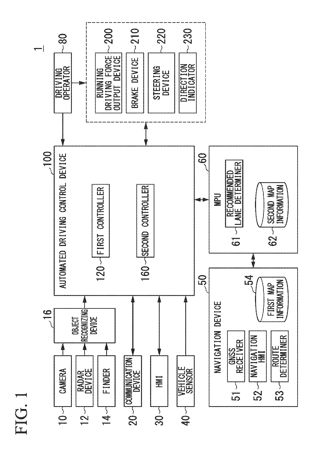
[0026]FIG. 1 is a configuration diagram of a vehicle system 1 using a vehicle control device according to an embodiment. A vehicle in which the vehicle system 1 is mounted is, for example, a vehicle having two wheels, three wheels, four wheels, or the like, and a driving source thereof is an internal combustion engine such as a diesel engine or a gasoline engine, an electric motor, or a combination thereof. In a case in which an electric motor is included, the electric motor operates using power generated using a power generator connected to an internal combustion engi...

second embodiment

[0070]Hereinafter, a second embodiment will be described. As the configuration diagrams, FIGS. 1 and 2 will be cited. Hereinafter, points different from the first embodiment will be described in detail with reference to FIG. 7. FIG. 7 is a flowchart illustrating an example of a process according to a second embodiment. The same reference sign will be assigned to each process that is the same as that illustrated in FIG. 4, and description thereof will not be presented here.

[0071]Steps S101 and S103 are similar to those of the flowchart illustrated in FIG. 4, and thus description thereof will not be presented. In a case in which it is determined by a road shoulder status determiner 145 that a plurality of other vehicles m are not running in line on a road shoulder in Step S105, and in a case in which it is determined that a subject vehicle M is immediately before a branching point Pb in Step S107, a branching control executer 147 controls a direction indicator 230 such that a directio...

third embodiment

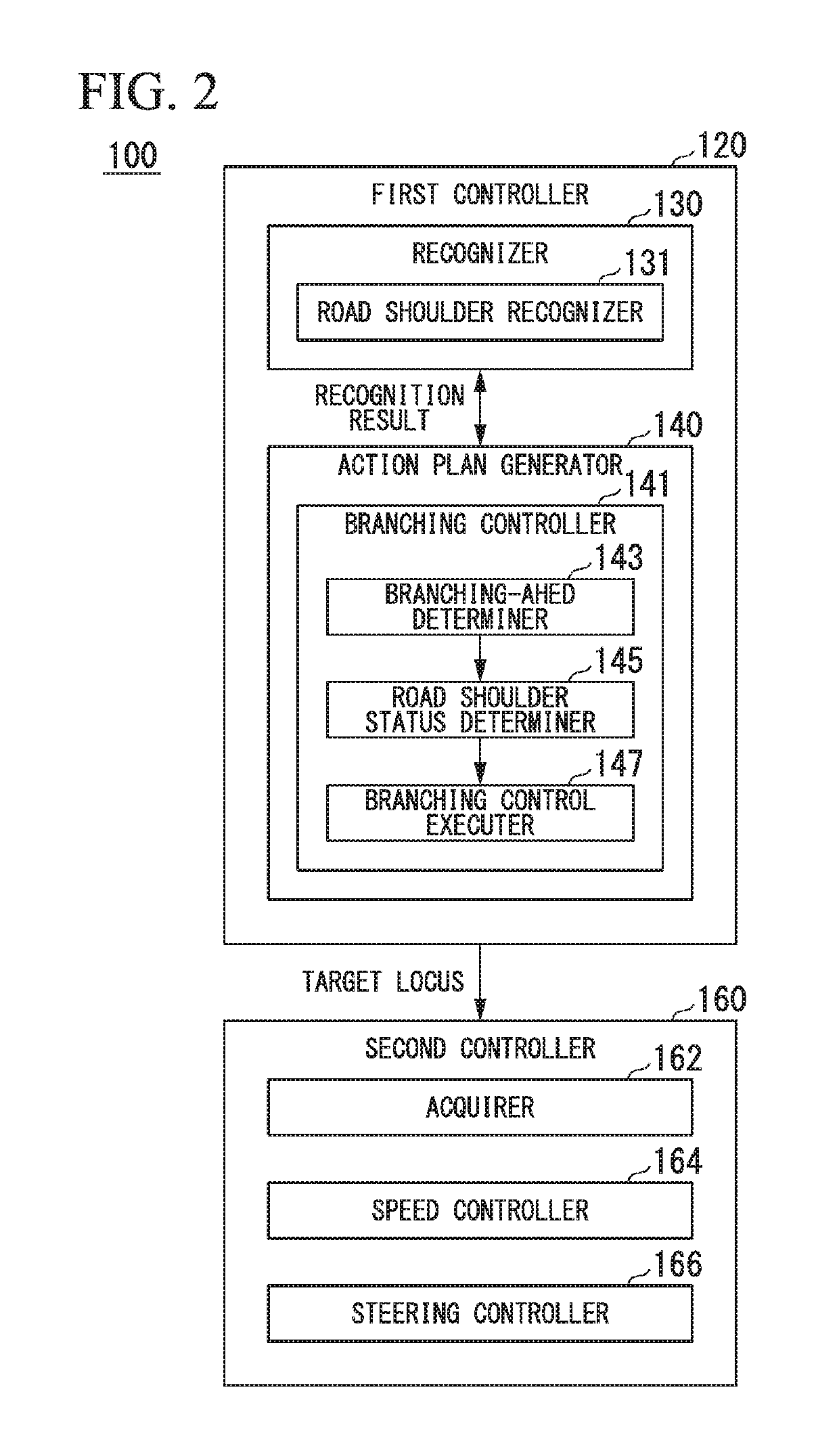
[0079]Hereinafter, an example in which a recognizer 130 and a branching controller 141 having the same functions and the same configurations as those of the first controller 120 described above are used in a vehicle having a driving supporting function will be described with reference to FIG. 9.

[0080]FIG. 9 is a configuration diagram of a vehicle system 1A in which a vehicle control device according to an embodiment is used in a vehicle having a driving supporting function. Functions and components that are similar to those of the vehicle system 1 will not be described here. The vehicle system 1A, for example, includes a driving supporting control unit300 in which some of the components included in the vehicle system 1 are changed. The driving supporting control unit 300 includes a recognizer 130, a branching controller 141, and a driving supporting controller 310. The configuration illustrated in FIG. 9 is merely one example, and thus, a part of the configuration may be omitted, or...


PUM


Abstract

A vehicle control device includes: a first recognizer recognizing, in the vicinity of a first vehicle, a plurality of second vehicles; a second recognizer recognizing a road shoulder of a road on which the first vehicle is present; and a controller executing driving control of controlling one or both of steering and acceleration / deceleration of the first vehicle, wherein the controller sets a degree of monitoring of one of the plurality of second vehicles present on a road shoulder in a section from a branching point to a point a predetermined distance from the branching point, to be higher than another of the plurality of second vehicles present on a road shoulder out of the section.

Description

CROSS-REFERENCE TO RELATED APPLICATION[0001]Priority is claimed on Japanese Patent Application No. 2017-215714, filed Nov. 8, 2017, the content of which is incorporated herein by reference.BACKGROUND OF THE INVENTIONField of the Invention[0002]The present invention relates to a vehicle control device, a vehicle control method, and a storage medium.Description of Related Art[0003]Conventionally, technologies for detecting a road shoulder having a space in which a vehicle can stop and controlling driving such that the vehicle stops on the detected road shoulder in a case in which disaster information is received have been disclosed (for example, see Japanese Unexamined Patent Application, First Publication No. 2010-20371).SUMMARY OF THE INVENTION[0004]In conventional technologies, bringing a vehicle onto a road shoulder in the case of a non-emergency time has not been taken into consideration. However, there are cases in which, near an exit of an expressway or the like, a road shoulde...

Claims


Application Information

Patent Timeline
Patent Type & Authority Applications(United States)
IPC IPC(8): B60W30/165G05D1/00G06K9/00B60W40/06B60W40/04
CPCB60W30/165G05D1/0088G06K9/00798G06K9/00805B60W40/06B60W40/04G05D2201/0213B60W30/18163B60W30/18154B60W30/12B60W2540/20B60W10/06B60W10/184B60W10/20B60W2720/106B60W2552/00B60W2552/30B60W2554/00B60W2556/50G06V20/588G06V20/58
Inventor MIURA, HIROSHIISHIKAWA, MAKOTOTSUCHIYA, MASAMITSUKAWABE, KOJI
Owner HONDA MOTOR CO LTD
Why Eureka
Try Eureka