Mounting Assembly

a technology of mounting assembly and frame, which is applied in the direction of protective equipment, weapons, armour, etc., can solve the problems of affecting the safety of crew members, unable to permit minor deflection of the frame, and damage to adjacent frame sections and/or locking against adjacent frame sections, etc., to achieve the effect of minor deflection

Inactive Publication Date: 2019-05-09
AMSAFE BRIDPORT LTD
View PDF27 Cites 0 Cited by
  • Summary
  • Abstract
  • Description
  • Claims
  • Application Information

AI Technical Summary

Benefits of technology

[0009]A mounting assembly according to the present invention offers the advantage that the arm is not rigidly attached to the base, and is capable of minor deflection before returning to its “normal”, in use, position. So long as the applied force is less than a pre-determined value, the arm will deflect and then return to its normal position. This is particularly advantageous in enabling the mounting assembly to cope with the general knocks that it may receive in normal use, for example, when it is used to mount a net-based armour system to a vehicle. In this case the mounting assembly should be able to deflect when it comes into contact with obstacles, for example roadside obstacles, and then return to its normal position. A further advantage of a mounting assembly according to the present invention is that the biasing force can be manually overcome—by applying a force greater than the pre-determined value—to move the arm into a “storage” position.
[0034]A mounting assembly according to the present invention offers the advantage that the arm is not rigidly attached to the base, and is capable of minor deflection before returning to its “normal”, in use, position. This is particularly advantageous in enabling the mounting assembly to cope with the general knocks that it may receive in normal use, for example, when it is used to mount a net-based armour system to a vehicle. In this case the mounting assembly should be able to deflect when it comes into contact with obstacles, for example roadside obstacles, and then return to its normal position.
[0040]In an embodiment of the invention a defensive shield is mounted on the mounting assemblies. In an embodiment of the invention a net-based armour system is mounted on the mounting assemblies. The present inventors have identified the mounting assembly according to the present invention as offering particular advantages over currently available apparatus for mounting defensive shields, such as net-based armour systems, onto vehicles.

Problems solved by technology

Such frames function well in supporting the net, but can distort if heavily loaded, for example, when subjected to a hit from a projectile such as an RPG, or when striking or being struck by an object during use of the vehicle, e.g. hitting a wall when the vehicle is being driven.
Such distortion can result in a “domino effect”, causing damage to adjacent frame sections and / or locking against adjacent frame sections.
This has the potential to be very dangerous to crew members operating in dangerous situations, as it can prevent them from being able to safely exit the vehicle, as well as preventing the net-based armour from functioning properly.
Furthermore, it does not permit minor deflections of the frame, as the arm cannot move until the shear pin has broken and then it is free to move into a collapsed position.

Method used


Image

  • Mounting Assembly
  • Mounting Assembly
  • Mounting Assembly

Examples


first embodiment

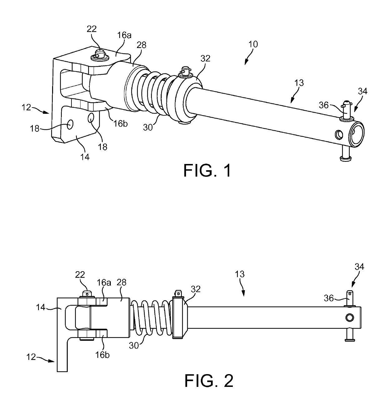
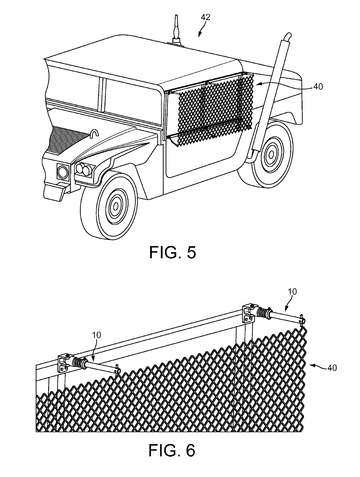
[0057]FIG. 1 shows a perspective view of a mounting assembly 10 according to the present invention. A mounting assembly 10 according to the present invention can be used for a wide variety purposes. In general, the mounting assembly 10 can be used in any application where it is desired to mount one object onto another. In the present case the mounting assembly 10 will be described in terms of an assembly for mounting a net-based armour system onto a vehicle, but it is noted that this is merely one possible application, and the invention is not limited in this way.

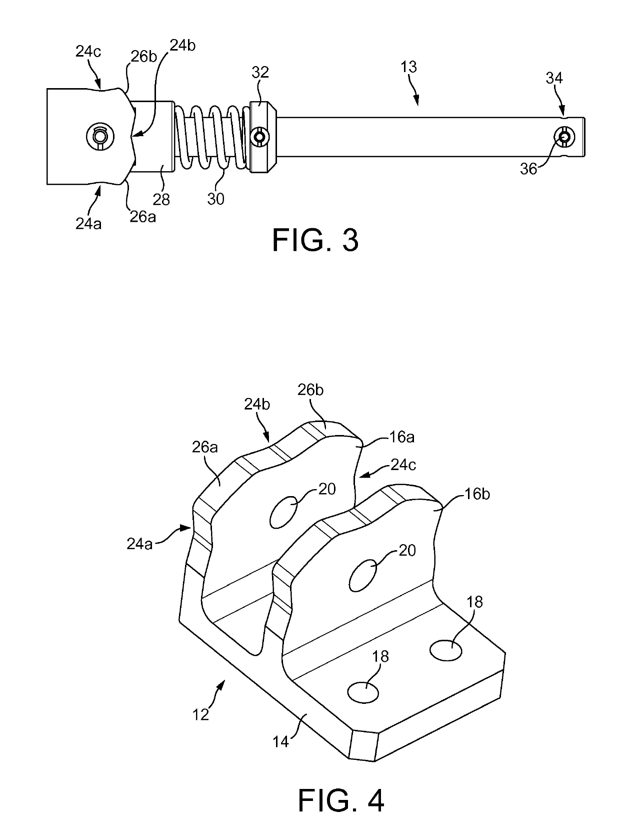
[0058]FIGS. 1-3 show a mounting assembly 10 according to the present invention. The mounting assembly 10 comprises a base plate 12, and an arm 13 pivotally mounted on the base plate 12. In use the arm 13 is capable of pivoting between three distinct positions, as will be described in more detail below.

[0059]The base plate 12, which can be best viewed in FIG. 4 comprises a planar section 14 and a pair of parallel cam surface...

second embodiment

[0072]FIGS. 7-10 show a mounting assembly 100 according to the present invention. The mounting assembly 100 shares many features in common with the mounting assembly 10 of FIG. 1, and like parts will be numbered the same but increased by 100.

[0073]The mounting assembly 100 can be used for a wide variety purposes. In general, the mounting assembly 100 can be used in any application where it is desired to mount one object onto another. In the present case the mounting assembly 100 will be described in terms of an assembly for mounting a net-based armour system onto a vehicle, but it is noted that this is merely one possible application, and the invention is not limited in this way.

[0074]FIG. 7 shows a perspective view of the mounting assembly 100. The mounting assembly 100 comprises a base plate assembly 112, and an arm 113 pivotally mounted on the base plate 112. In use the arm 113 is capable of pivoting between two distinct positions relative to the base plate assembly 112, as will ...

third embodiment

[0089]FIGS. 11-14 show a mounting assembly 200 according to the present invention. The mounting assembly 200 shares many features in common with the mounting assembly 100 of FIGS. 7-10, and like parts will be numbered the same but increased by 100.

[0090]The mounting assembly 200 can be used for a wide variety purposes. In general, the mounting assembly 200 can be used in any application where it is desired to mount one object onto another. In the present case the mounting assembly 200 will be described in terms of an assembly for mounting a net-based armour system onto a vehicle, but it is noted that this is merely one possible application, and the invention is not limited in this way. The mounting assembly is particularly suited for mounting a net-based armour system at or near a corner of a vehicle or other structure, such that the arm 213 of the mounting assembly projects at an angle of approximately 135° to the surface on which it is mounted. This enables the net-based armour to...


PUM


Abstract

A mounting assembly, comprising: a base, for attaching the mounting assembly to a vehicle or structure; and an arm, connected to the base, for attaching an object to the mounting assembly, wherein the base is a two-part construction comprising a first part for attaching to a vehicle or structure and a second part for attaching to the arm, and wherein the second part is pivotally mounted on the first part

Description

CROSS-REFERENCE TO RELATED APPLICATION[0001]This application is a divisional application of co-pending U.S. patent application Ser. No. 13 / 752,887 filed Jan. 29, 2013 entitled “Mounting Assembly” by John Wood, which is incorporated by reference herein in its entirety.TECHNICAL FIELD[0002]The present invention relates to a mounting assembly, particularly, but not exclusively, to a mounting assembly for mounting a structure, such as a net-based armour system, to a vehicle.TECHNICAL BACKGROUND[0003]It is known to use net-based armour systems mounted to vehicles and other structures to defend against RPG attacks. The net-based armour does not prevent an RPG from hitting the vehicle, but if a nose cone of an RPG enters a mesh of the net it can deform the nose cone of the RPG and prevent the fuse from firing. This effectively neutralises the RPG and it becomes no more than a fast moving projectile, which will not be able to penetrate the armour of the vehicle.[0004]A number of mounting as...

Claims


Application Information

Patent Timeline
Patent Type & Authority Applications(United States)
IPC IPC(8): F16M13/02F41H5/013F41H5/02
CPCF16M13/02F41H5/013F41H5/026F41H5/02
Inventor WOOD, JOHN
Owner AMSAFE BRIDPORT LTD
Why Eureka
Try Eureka