Actuating device

a technology of actuating device and mounting plate, which is applied in the direction of mechanical control device, manual control with single controlling member, instruments, etc., can solve the problems of high cost, complex and expensive mounting, and actuating device known from the prior art, and achieves simple and cost-effective effect of large contact pressure for

Inactive Publication Date: 2013-02-19
ZF FRIEDRICHSHAFEN AG
View PDF33 Cites 3 Cited by
  • Summary
  • Abstract
  • Description
  • Claims
  • Application Information

AI Technical Summary

Benefits of technology

[0007]Against this background, the purpose of the present invention is to provide an actuating device with an actuating element, for example to actuate a manual transmission of a motor vehicle, by virtue of which the disadvantages of the prior art can be overcome. In particular, the actuating device should enable enduringly play-free guiding and mounting of the actuating element in the base housing of the actuating device, but should comprise a minimum of individual components and should enable substantial cost saving in its production and assembly.
[0011]In this way it is advantageously possible for the production accuracy of the ball stud and / or the ball socket to be reduced without adverse effect upon the quality and life of the actuating device, and without having to expect a less precise tactile “feel” of the actuating device. At the same time, moreover, a permanently play-free and rattle-free mounting and holding of the ball stud in the ball socket is ensured. Accordingly, not only the ball stud but in addition the actuating element—for example the selector lever of a vehicle transmission—is also held, free from play and without rattling, in the base housing of the actuating device.
[0014]Preferably, both the pressure contact element and the flexible elastic surface zone are made integrally with the ball socket half-shell. This enables exceptionally cost-effective production both of the ball socket and of the prestressing means formed by the flexible elastic surface zone and the pressure contact element, as a single piece. This is a decided advantage when the base housing of the actuating device or the ball socket half-shells are made of plastic, as in increasingly the case with actuating devices, for example in motor vehicles.
[0015]According to another preferred embodiment the base is formed essentially of two housing halves. In this case each of these two housing halves is formed integrally with one of the two respective ball socket half-shells. This reduces the production cost of the base housing of the actuating device still further, since thereby the housing, the shift lever mounting and the prestressing means for play-free mounting of the shift lever can all be made with only two, in each case integrally formed plastic half-shells. Furthermore, in this way a greatly simplified, play-free final assembly of the housing halves that comprise the ball socket—together with the joint ball and the shift lever—can take place without any need for subsequent adjustment of the shift lever mounting. Compared with the prior art, this saves considerable costs.
[0017]This embodiment also enables the prestressing means together with the associated socket half-shell to be designed and produced in a particularly simple and cost-effective manner.
[0018]The design of the flexible elastic surface zone in accordance with the above embodiment as a membrane clamped essentially all the way round, is particularly advantageous in that, in this way, it results in sufficiently large contact pressure forces between the pressure contact element and the ball stud even with minimal deflection of the membrane. This is because when the membrane is deflected, owing to the clamping of the membrane around the whole of its outer circumference substantial tensile forces are produced in the plane of the membrane, whereby in turn the restoring force exerted by the membrane and needed to ensure play-free holding of the ball stud acts perpendicularly to the plane of the membrane, in the direction toward the ball stud.

Problems solved by technology

However, especially since the mountings for such actuating levers are increasingly made from plastic, it is often difficult and comparatively complicated and expensive to create a mounting which on the one hand is free from play and on the other hand remains easy to manipulate.
However, such actuating devices known from the prior art are complex and therefore tend to be expensive, because they comprise numerous components and because they need to be adjusted and assembled with care so as to eliminate any play.

Method used


Image

  • Actuating device
  • Actuating device
  • Actuating device

Examples


Embodiment Construction

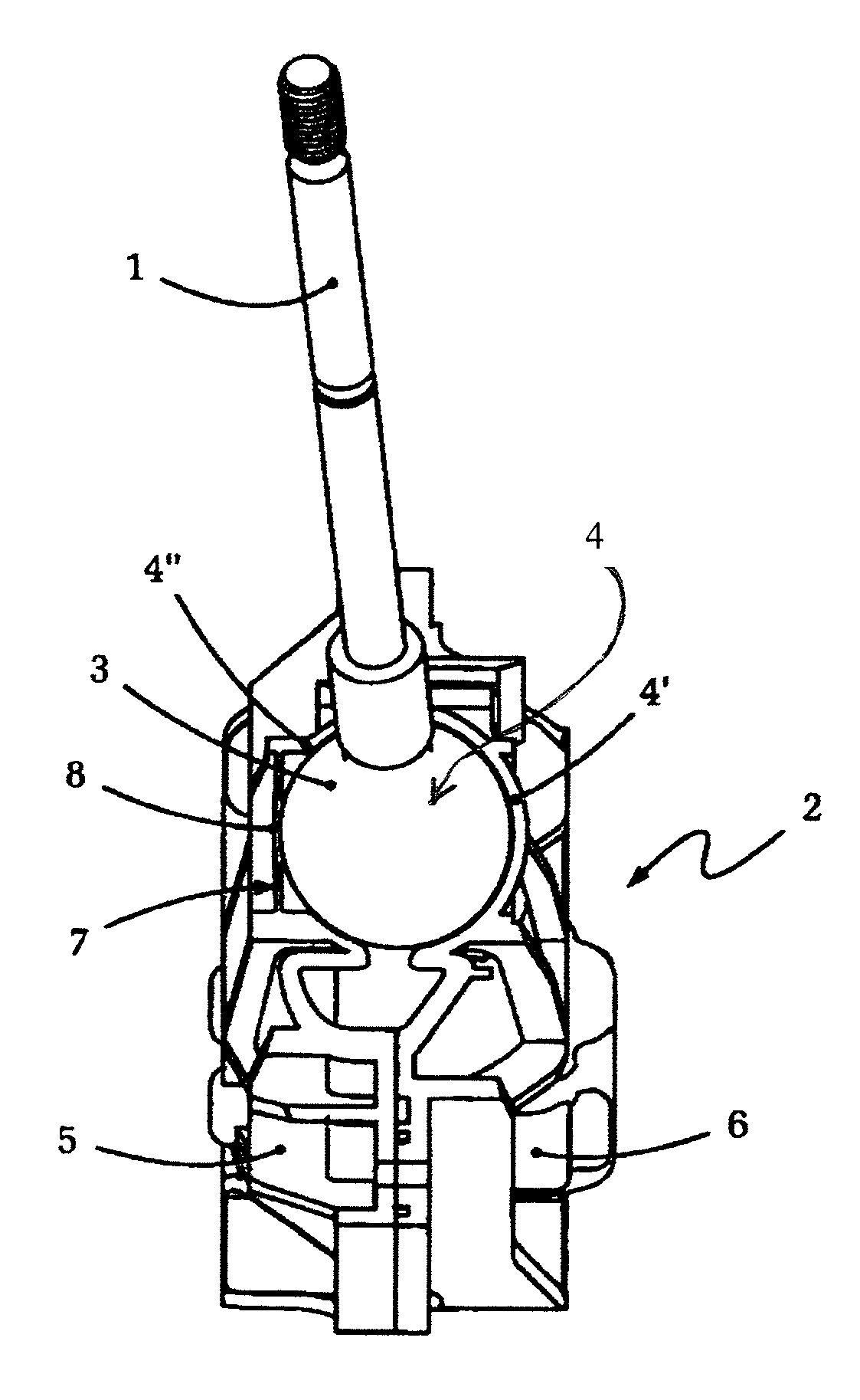
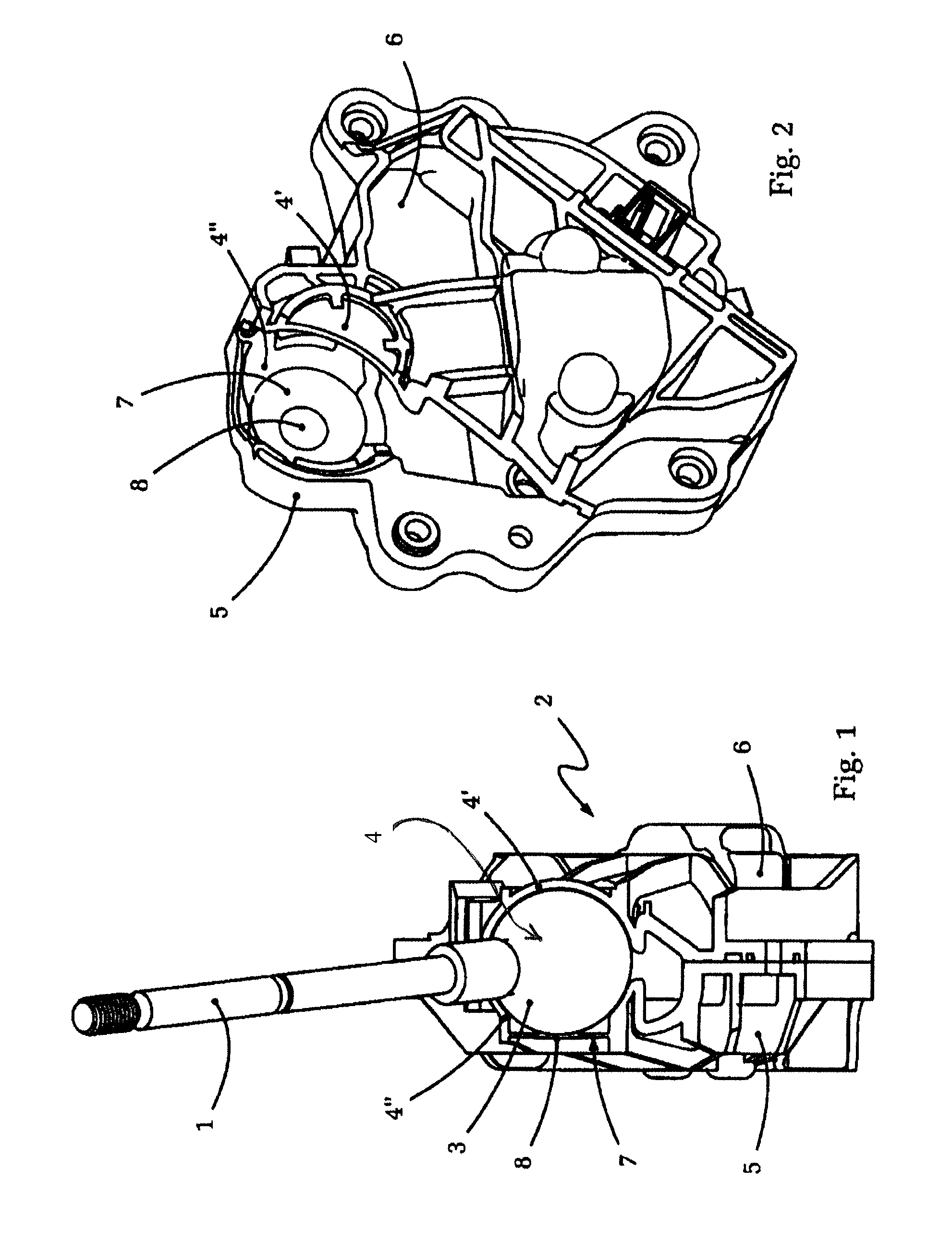
[0025]FIG. 1 shows a schematic, isometric view of an embodiment of an actuating device according to the present invention. This example embodiment is an actuating device or selector lever for an automated vehicle transmission.

[0026]In the representation shown in FIG. 1 can be seen, first, the actuating element in the form of a rod-shaped shift lever 1, this shift lever 1 being mounted by means of a ball-and-socket joint 3 so that it can pivot relative to a base housing 2. For this purpose the shift lever 1 is fixed to a ball stud 3 which, for its part, is held and can slide within a ball socket arranged in the base housing 2 of the actuating device.

[0027]Thus, the shift lever 1 can be moved forward and backward relative to the driving direction, as well as to one side and the other transversely to the driving direction, for example in order to select the various gates of the selector lever device or the various gear ratios of the automatic transmission.

[0028]In this case the ball so...


PUM


Abstract

An actuating device comprising an actuating element that is moved by a ball stud relative to a base comprising a ball socket. The actuating element can move relative to the base, within at least one pivot plane, between at least two shift positions. At least one recess of the ball socket has an elastic surface area which is flexible in the direction along the radius of the ball socket. The flexible elastic surface area has a centrally arranged pressure contact element, which bears against the joint ball. In a neutral position of the elastic surface area, the contact surface of the pressure contact element is at a distance away from the mid-point of the ball socket which is smaller than the radius of the joint ball, such that it possible to produce actuating devices which are robust in operation and free from play.

Description

[0001]This application is a National Stage completion of PCT / DE2008 / 000202 filed Feb. 5, 2008, which claims priority from German patent application serial no. 10 2007 008 961.0 filed Feb. 21, 2007.FIELD OF THE INVENTION[0002]The invention concerns an actuating device for the manual actuation, in particular, of a gearshift transmission.BACKGROUND OF THE INVENTION[0003]Actuating devices of this type are used, for example but by no means exclusively, for the manual selection of gear ratios or for gear preselection in gearshift transmissions of motor vehicles. With such actuating devices, which can consist in particular of an actuating or selector lever for an automatic transmission, positioned between the front seats of a motor vehicle, it is important to ensure that the actuating lever is mounted as free from play as possible so that the various functional positions of the actuating lever can be engaged by the operator or driver of the vehicle confidently and with trustworthy tactile ...

Claims


Application Information

Patent Timeline
Patent Type & Authority Patents(United States)
IPC IPC(8): B60K20/00F16C11/00G05G9/00F16H59/04
CPCF16C11/0638F16C11/069F16C11/086F16H59/0208Y10T74/20165Y10T403/32786Y10T74/20Y10T74/2014Y10T74/20018F16H2059/0269B60K20/02F16C11/06F16H59/02
Inventor GR. KOHORST, BERTHOLD
Owner ZF FRIEDRICHSHAFEN AG
Why Eureka
Try Eureka