Front opening wafer container with door deflection minimization

a technology of front opening wafer and container, which is applied in the direction of liquid handling, packaging goods, caps, etc., can solve the problems of affecting the integrity of the seal between the door and the door frame, the distortion of the container, etc., and achieves the effect of minimizing the weight of the container, minimizing the sag of the wafer, and improving the sealing characteristics

Inactive Publication Date: 2013-10-24
ENTEGRIS INC
View PDF2 Cites 2 Cited by
  • Summary
  • Abstract
  • Description
  • Claims
  • Application Information

AI Technical Summary

Benefits of technology

[0013]Accordingly, it would be desirable to develop front opening configurations for 450 mm wafer containers that have design attributes for minimizing wafer sag and minimizing weight of the container. In addition, configurations providing improved sealing characteristics for the doors would be desirable. Moreover, configurations providing enhanced wafer support to accommodate storing of 450 mm wafers in wafer containers as well during robotic handling of the wafers would be desirable.

Problems solved by technology

An issue heretobefore unrecognized is that the weight of the wafers engaged with the cushion on the front door can cause a considerable force component in the z direction causing distortion of the containers in the z direction primarily exhibited by an outward flexing of the door as well as the rear wall.
It has been discovered that this force can cause door deflection issues that can affect the integrity of the seal between the door and door frame, particularly in the context of 450 mm wafer containers.

Method used


Image

  • Front opening wafer container with door deflection minimization
  • Front opening wafer container with door deflection minimization
  • Front opening wafer container with door deflection minimization

Examples


Embodiment Construction

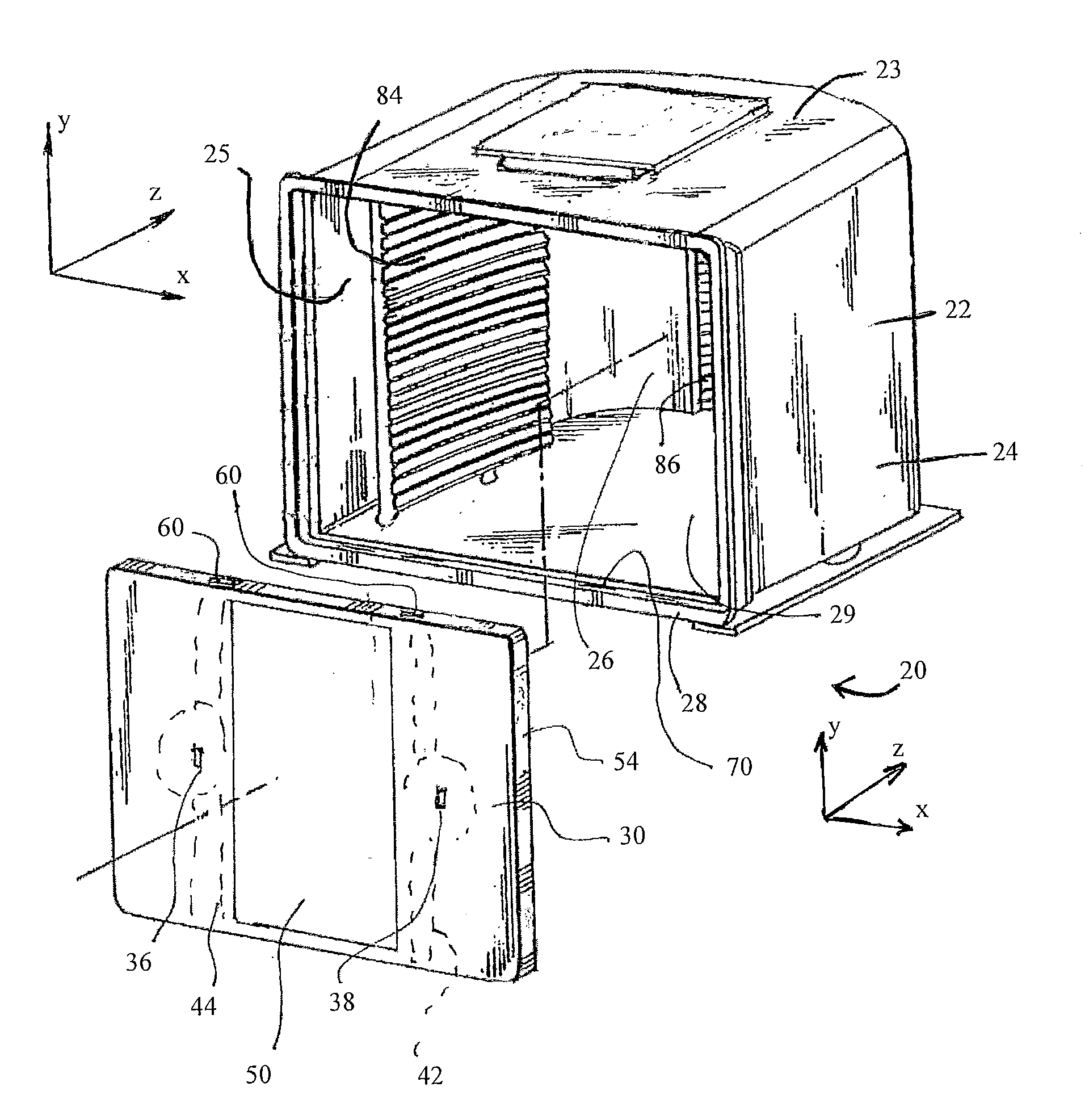
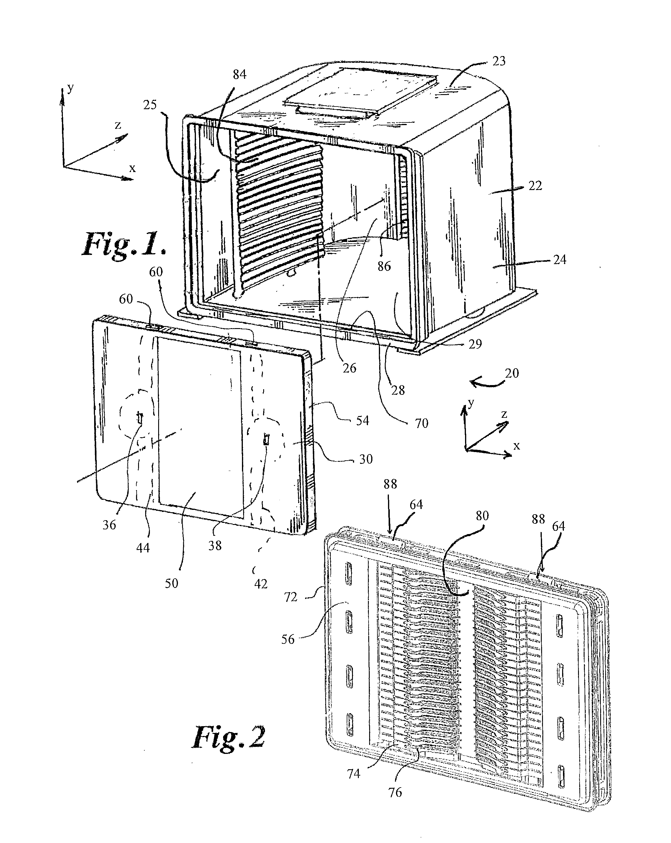
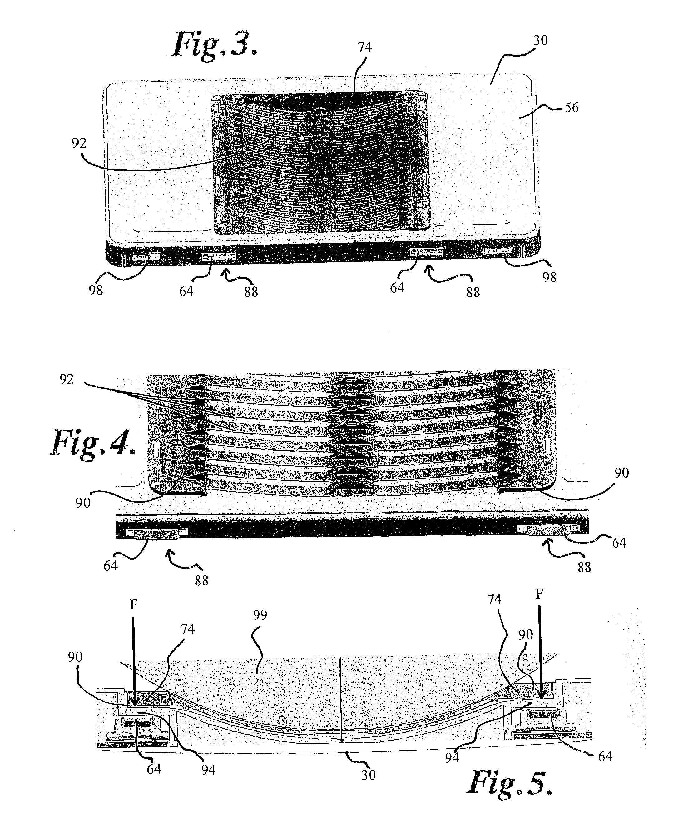
[0032]Referring to the figures, a front opening wafer container 20 is illustrated and comprises generally a container portion 22, having a top wall 23, a pair of side walls 24, 25, a back wall 26, a door frame 28 defining a front opening 29, and a front door 30 configured to close the open front. The door has a pair of key holes 36, 38 that access latch mechanisms 42 located inside the door housing 44. Such latch mechanisms can be generally configured as illustrated in U.S. Pat. Nos. 4,995,430; 7,182,203; or 7,168,587, all of which are owned by the owner of the instant application, and all are incorporated herein by reference. The door has an outside surface 50, a periphery 54, and an inside surface 56. Slots 60 are positioned on the periphery and allow latching tabs 64 or tips to extend and retract from the door to engage and disengage recesses 70 on the inside surface of the door frame. A seal or gasket 72 follows the circumference of the door and engages with the door frame to se...


PUM


Abstract

A front opening wafer container suitable for 450 mm diameter wafers. The front door has a pair of latch mechanism externally operable on the sides of the door, each latching mechanism having a pair of latch tips extendible from top and bottom peripheries of the door into receivers in the door frame of the front opening of the container portion. The door contains wafer cushions that support horizontally stacked wafers. The cushions have vertically extending support strip regions with arcuate wafer engagement portions therebetween. The arcuate wafer engagement portion is positioned in a vertically extending central recess on the inside surface of the door. The wafer cushion is secured to the inside of the door at the pair of vertically extending support strip portions at a pair of vertically extending loading junctures. The latching tips of each latching mechanism is in a vertical alignment with the vertically extending loading junctures.

Description

RELATED APPLICATIONS[0001]The present application is a National Phase entry of PCT Application No. PCT / US2011 / 056921, filed Oct. 19, 2011, which claims priority to U.S. Provisional Application Ser. No. 61 / 394,770, filed Oct. 20, 2010, the disclosures of which are hereby incorporated by reference herein in their entirety.BACKGROUND OF THE INVENTION[0002]Integrated circuits such as computer chips are manufactured from silicon wafers. The silicon wafers need to be maintained in extremely clean and contamination free environments during their transport and in between manufacturing process steps. Additional, required or desirable characteristics of containers to transport and / or store semiconductor wafers include light weight, rigidity, cleanliness, limited gaseous emissions, and cost effective manufacturability. The containers provide hermetic or close to hermetic isolation of wafers when the containers are closed. Simply stated, such containers need to keep the wafers clean, uncontamin...

Claims


Application Information

Patent Timeline
Patent Type & Authority Applications(United States)
IPC IPC(8): H01L21/677
CPCH01L21/67772H01L21/67369H01L21/67373H01L21/673B65D85/00B65D85/38
Inventor FULLLER, MATTHEW A.
Owner ENTEGRIS INC
Why Eureka
Try Eureka