Method and device for operating capacitive touch panel

a capacitive touch and touch technology, applied in the direction of instruments, computing, electric digital data processing, etc., can solve the problems of increasing power consumption and limit of driving duration, and achieve the effect of reducing power consumption and increasing power consumption

Active Publication Date: 2019-05-09
MIRAENANOTECH
View PDF3 Cites 7 Cited by
  • Summary
  • Abstract
  • Description
  • Claims
  • Application Information

AI Technical Summary

Benefits of technology

[0012]According to the present invention, whereas duration assigned to each transmission electrode decreases with increasing number of transmission electrodes in the conventional scan driving method in which a signal is sequentially applied to all transmission electrodes, sufficient duration may be assigned to a single transmission electrode and touch position accuracy may be increased through multiple samplings, in the coarse / fine sensing method.
[0013]Also, whereas power consumption increases with increasing number of transmission electrodes in the conventional multi-line selection driving method in which a signal is simultaneously applied to all transmission electrodes, power consumption may be decreased in the coarse / fine sensing method according to the present invention because a first analysis position is detected and multiple samplings are performed only at the first analysis position.
[0014]Technical effects of the present invention are not limited to the effects mentioned afore, and unmentioned other technical effects may clearly be understood by a person of ordinary skill in the art from the hereinafter description.

Problems solved by technology

However, in the scan driving method, with increasing resolution of the capacitive touch panel, there may be a limitation imposed on driving duration, and in the multi-line selection driving method, there is a disadvantage of increased power consumption due to having to simultaneously drive all channels.

Method used


Image

  • Method and device for operating capacitive touch panel
  • Method and device for operating capacitive touch panel
  • Method and device for operating capacitive touch panel

Examples


embodiment

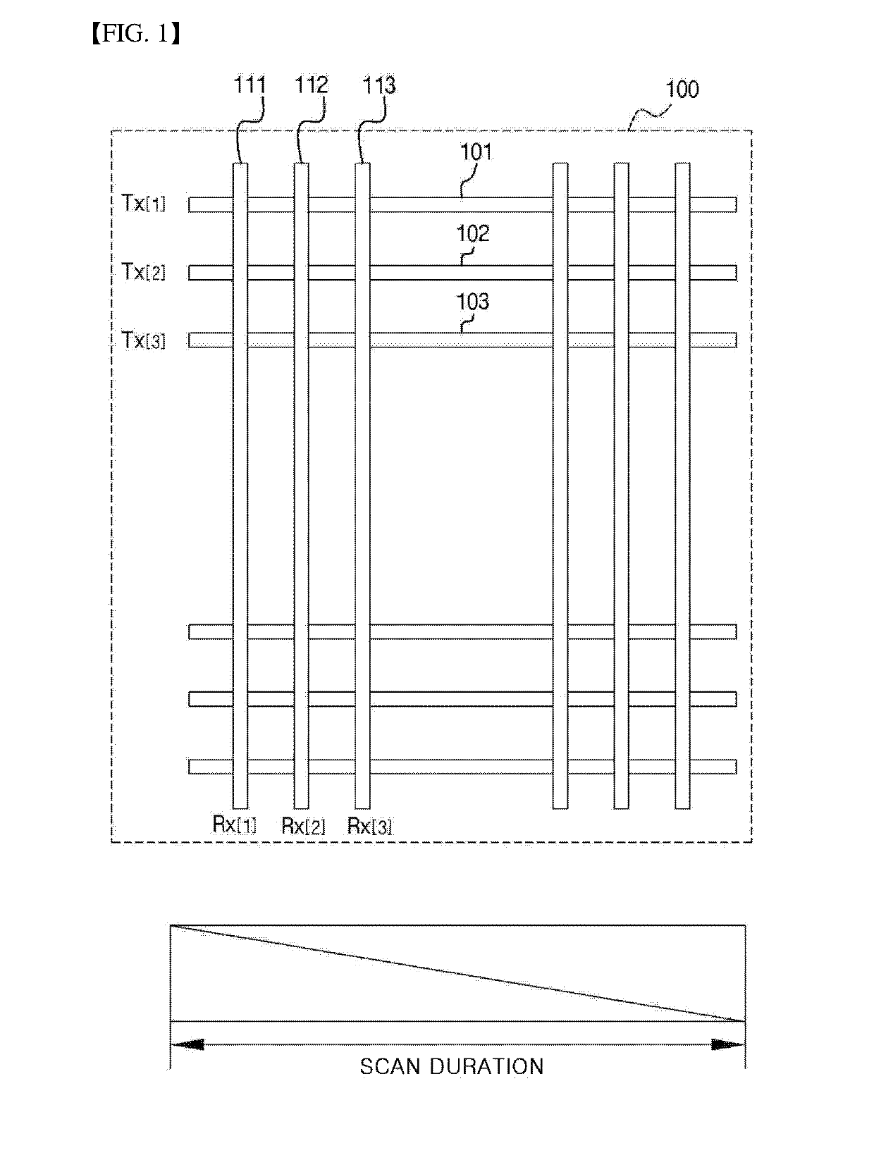
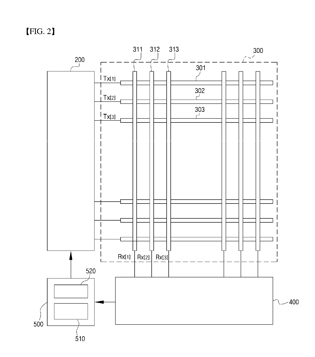
[0024]FIG. 2 is a block diagram for explaining a touch panel operation device according to an embodiment of the present invention.

[0025]Referring to FIG. 2, a touch panel device includes a driver 200, a touch sensor 300, a receiving processor 400, and a coarse / fine sensing processor 500, and the coarse / fine sensing processor 500 includes a discriminator 510 and a controller 520.

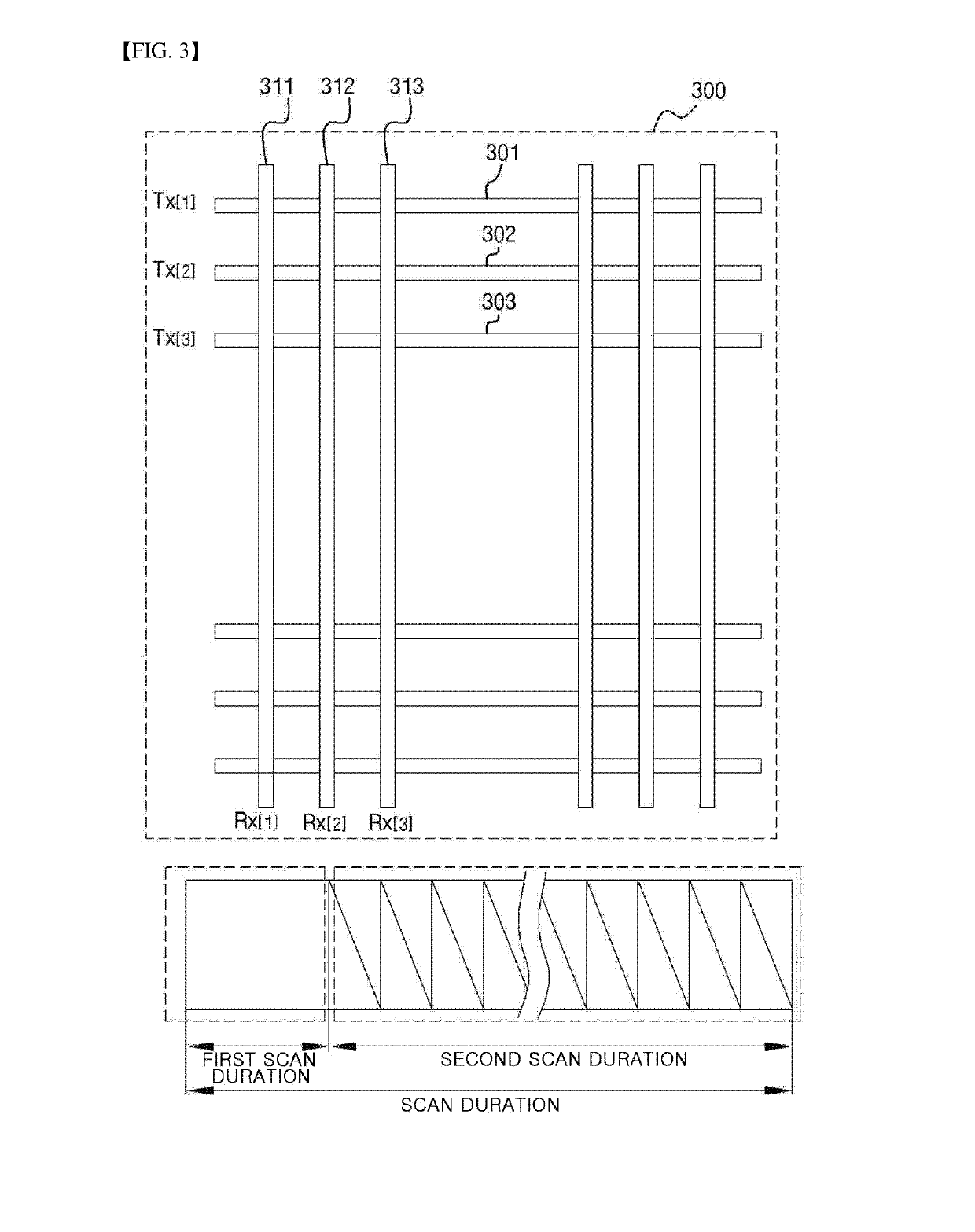
[0026]The driver 200 applies a transmission signal to a plurality of transmission electrodes 301, 302, 303 for discriminating a touch action detection using a coarse / fine sensing method having a first scan (coarse sensing duration) and a second scan (fine sensing duration). During the first scan, a transmission signal is applied sequentially or simultaneously to a plurality of transmission electrodes 301, 302, 303 divided into groups, and during the second scan, a transmission signal is applied sequentially or simultaneously to a first analysis position determined during the first scan.

[0027]The touch sensor ...


PUM


Abstract

In the touch panel device and the operating method for the same according to the present invention, an entire scan is divided into a first scan and a second scan for determining a touch position. In the first scan, a plurality of transmission electrodes are configured into groups, and a signal is applied sequentially or simultaneously such that a first analysis position is determined. In the second scan, since a signal is sequentially or simultaneously applied only to the first analysis position, a plurality of sampling durations can sufficiently be provided such that a second analysis position, which is the exact touch position, can be determined.

Description

TECHNICAL FIELD[0001]The present invention relates to a method and a device for operating a capacitive touch panel and, more particularly, to a coarse / fine sensing method in which a second analysis position is determined by determining a first analysis position through a first scan and performing a second scan in which a signal is applied only to the first analysis position determined through the first scan.BACKGROUND ART[0002]Personal computers, mobile communications devices, and other personal information processing devices, etc. each utilize various input devices, such as a keyboard, mouse, digitizer, etc. for user interfacing. With expanding mobile communications device development, because it is difficult to make a complete product with input devices such as the keyboard and mouse, there is an ever-increasing need for input devices which are simpler, can reduce occurrence of malfunction, and are portable. Responding to such a need, a touch panel is proposed in which information...

Claims


Application Information

Patent Timeline
Patent Type & Authority Applications(United States)
IPC IPC(8): G06F3/041G06F3/044
CPCG06F3/0416G06F3/044G06F3/0446G06F3/041661
Inventor KWON, OH-KYONG
Owner MIRAENANOTECH
Why Eureka
Try Eureka