Liquid discharge head and channel structure

a liquid discharge head and channel technology, applied in printing and other directions, can solve the problems of channel members themselves fatigue and strength degradation, and achieve the effect of suppressing the deformation of the channel, reducing the stress applied, and suppressing the entry of small foreign matter into the channel

Active Publication Date: 2019-05-16
SEIKO EPSON CORP
View PDF0 Cites 0 Cited by
  • Summary
  • Abstract
  • Description
  • Claims
  • Application Information

AI Technical Summary

Benefits of technology

[0006]It is preferable that all of the plurality of openings be closed by lid members having the air permeability. According to this form, all of the plurality of openings are closed by the lid members having the air permeability. Thus, the air in the channel or the openings easily passes through the lid members. This can reduce stress applied to the channel member due to the expansion or contraction of the air in the channel or the openings.
[0007]It is preferable that a diameter of at least one air hole of the at least one of the lid members having the air permeability be 1/100 to 1/10 of a minimum width of a section of the channel. According to this form, the diameter of the at least one air hole of the at least one of the lid members having the air permeability is 1/100 to 1/10 of the minimum width of the section of the channel. Thus, even when the openings are closed by the lid members, the air easily passes while foreign matter is unlikely to enter.
[0008]It is preferable that the at least one air hole include a plurality of air holes, and an average diameter of the plurality of air holes of the at least one of the lid members having the air permeability be 10 nm to 100 μm. According to the above-described form, the average diameter of the plurality of air holes of the at least one of the lid members having the air permeability is 10 nm to 100 μm. Thus, the lid member allows the air in the channel to pass therethrough and entry of small foreign matter into the channel can be suppressed.
[0009]It is preferable that the at least one of the lid members having the air permeability have a Gurley value of 0.5 to 2000 s/100 mL. According to the above-described form, the at least one of the lid members having the air permeability has a Gurley value of 0.5 to 2000 s/1

Problems solved by technology

In such a case, depending on the material of the protective films or the method of closing the openings communicating with the outside, simply closing the openings by the protective films may result in, due to variation in atmosphe

Method used


Image

  • Liquid discharge head and channel structure
  • Liquid discharge head and channel structure
  • Liquid discharge head and channel structure

Examples


first embodiment

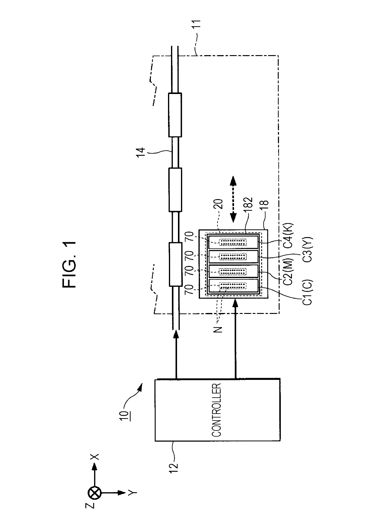
[0031]FIG. 1 illustrates a structure of part of a liquid discharge apparatus 10 according to a first embodiment of the invention. The liquid discharge apparatus 10 according to the first embodiment is an ink jet printer in which ink that exemplifies liquid is discharged to a medium 11 such as a sheet of printing paper. The liquid discharge apparatus 10 illustrated in FIG. 1 includes a controller 12, a transport mechanism 14, a carriage 18, and a liquid discharge head 20. The controller 12 performs centralized control on the elements of the liquid discharge apparatus 10.

[0032]The transport mechanism 14 transports the medium 11 in the Y direction (sub-scanning direction) under the control of the controller 12. The carriage 18 reciprocates in the X direction (main scanning direction) under the control of the controller 12. Along with the transportation of the medium 11 and the reciprocation of the carriage 18, the liquid discharge head 20 discharges the ink to the medium 11. Thus, a de...


PUM


Abstract

A channel structure includes a channel is formed in a channel member and a plurality of openings that allow the channel to communicate with an outside. The plurality of openings are closed by respective lid members. At least one of the lid members that closes at least one of the plurality of openings has air permeability.

Description

BACKGROUND1. Technical Field[0001]The present invention relates to a technique of discharging liquid such as ink.2. Related Art[0002]A liquid discharge head that discharges liquid such as ink from nozzles has plurality of channels. For example, JP-A-2015-163440 discloses a liquid discharge head formed by laminating channel members in which a plurality of channels are formed. Some channel members have openings that allow the channels inside the channel members to communicate with the outside. Examples of such openings include, for example, nozzles. Thus, when the liquid discharge head or the channel members are transported, the openings communicating with the outside may be closed by protective films so as to suppress entry of foreign matter into the channels during transportation.[0003]Meanwhile, the component may be transported under an environment where the atmospheric pressure or temperature largely varies such as an environment during an airlift. In such a case, depending on the...

Claims


Application Information

Patent Timeline
IPC IPC(8): B41J2/14
CPCB41J2/1433B41J2/14233B41J2002/14362B41J2002/14419
Inventor ZHANG, JUNHUA
Owner SEIKO EPSON CORP
Why Eureka
Try Eureka