Electrical insulating structure producing method, electrical insulating structure and rotating electrical machine

Active Publication Date: 2019-05-16
TOSHIBA MITSUBISHI-ELECTRIC IND SYST CORP
View PDF4 Cites 2 Cited by
  • Summary
  • Abstract
  • Description
  • Claims
  • Application Information

AI Technical Summary

Benefits of technology

[0012]The present invention has been made based on the above findings, and an object there

Problems solved by technology

When an unequal electric field portion occurs due to application of an electric field to an insulator, and the electric field at that portion exceeds an ins

Method used


Image

  • Electrical insulating structure producing method, electrical insulating structure and rotating electrical machine
  • Electrical insulating structure producing method, electrical insulating structure and rotating electrical machine
  • Electrical insulating structure producing method, electrical insulating structure and rotating electrical machine

Examples


first embodiment

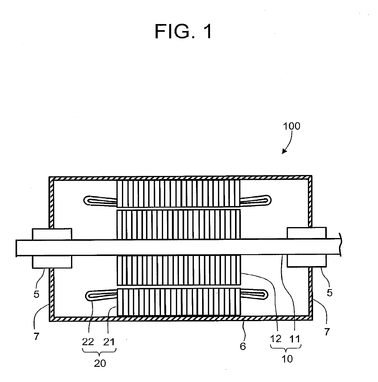
[0035]FIG. 1 is a sectional longitudinal view illustrating the configuration of a rotating electrical machine according to a first embodiment. A rotating electrical machine 100 has a rotor 10, a stator 20, a frame 6 surrounding the radially outside of the rotor 10 and the stator 20, and bearing brackets 7 attached to both axial ends of the frame 6.

[0036]The rotor 10 has a rotor shaft 11 extending in its longitudinal direction and a rotor core 12 attached to radially outside the rotor shaft 11. The rotor shaft 11 is rotatably supported at both axial sides thereof by bearings 5. Each of the bearings 5 is stationarily supported by each of the bearing brackets 7.

[0037]The stator 20 has a stator core 21 disposed radially outside the rotor core 12 so as to be spaced therefrom and stator windings 22 penetrating inside the stator core 21.

[0038]A plurality of stator slots (not illustrated) are formed along the inner surface of the stator core 21 with circumferential intervals therebetween an...

second embodiment

[0094]FIG. 15 is a flowchart illustrating the procedure of an electrical insulating structure producing method according to a second embodiment. This embodiment is a modification of the first embodiment. In this embodiment, instead of Step S24 of the first embodiment of forcedly applying impregnating macromolecular polymer, nanoparticle-containing impregnating macromolecular polymer that contains nanoparticles or has been mixed and kneaded with nanoparticles is injected (Step S31). In other respect, the second embodiment is identical to the first embodiment.

[0095]FIG. 16 is a sectional elevational view illustrating a state of injecting step of a nanoparticle-containing impregnating macromolecular polymer in the electrical insulating structure producing method according to the second embodiment. After Step S23 in which a vessel 61 of the impregnation apparatus 60 has been evacuated, the windings-incorporated object 90 is immersed in a nanoparticle-containing impregnating macromolecul...


PUM


Abstract

A producing method is for an electrical insulating structure covering an outer surface of a to-be-insulated object. The electrical insulating structure producing method comprises: a sheet production step of producing a main insulating sheet in which nanoparticles have been mixed; a cutting step in which the main insulating sheet is cut into main insulation tapes; a taping step of winding each of main insulation tapes on outside of the to-be-insulated object to produce a tape-wound to-be-insulated object in which a main insulated part is formed; a vacuum drawing step of vacuum drawing the tape-wound to-be-insulated object; an impregnation step of injecting a impregnating macromolecular polymer to impregnate the main insulated part in the tape-wound to-be-insulated object, and a solidifying step of raising the temperature of the insulated part to solidify the macromolecular polymer containing the nanoparticles.

Description

CROSS-REFERENCES TO RELATED APPLICATIONS[0001]The present application is a continuation application of International Application No. PCT / JP2016 / 003164 filed on Jul. 1, 2016, the entire content of which is incorporated herein by reference.BACKGROUND OF THE INVENTION[0002]The present invention relates to an electrical insulating structure producing method, an electrical insulating structure, and a rotating electrical machine.[0003]When an unequal electric field portion occurs due to application of an electric field to an insulator, and the electric field at that portion exceeds an insulation-breakdown limit voltage, a local breakdown is caused there. When the local breakdown progresses dendritically, an electric tree is generated. The electric tree is believed to be generated by starting from a high electric field concentration parts such as foreign matters, an air gap between an electrode and the insulator, foreign matters, projections and voids in the insulator.[0004]In recent years...

Claims


Application Information

Patent Timeline
IPC IPC(8): H02K3/40H02K3/30H02K15/10H02K15/12H02K7/08H01B19/04H01B19/02H01B17/62
CPCH02K3/40H02K3/30H02K15/105H02K15/12H02K7/083H01B19/04H01B19/02H01B17/62H01B13/00
Inventor MURA, KOTAROKIKUTA, SHINSUKETSUDA, TOSHIHIROYOSHIMITSU, TETSUO
Owner TOSHIBA MITSUBISHI-ELECTRIC IND SYST CORP
Why Eureka
Try Eureka