Vacuum loss detection during laser eye surgery

a laser eye surgery and vacuum loss technology, applied in laser surgery, medical science, surgery, etc., can solve the problems of progressive vision loss, near-sightedness (myopia), and increased lens power, so as to avoid imparting undesirable forces

Active Publication Date: 2019-05-23
AMO DEVMENT
View PDF0 Cites 7 Cited by
  • Summary
  • Abstract
  • Description
  • Claims
  • Application Information

AI Technical Summary

Benefits of technology

[0008]Improved laser eye surgery systems, and related methods, are provided. The laser eye surgery systems use a laser to form precise incisions in the cornea, in the lens capsule, and / or in the crystalline lens nucleus. In a preferred embodiment, a laser eye surgery system includes a laser cutting subsystem to produce a laser pulse treatment beam to incise tissue within the eye. An optical coherence tomography (OCT) scanning subsystem to measure the spatial disposition of external and internal structures of the eye in which incisions can be formed. The laser eye surgery system further includes an alignment subsystem, shared optics operable to scan the treatment beam, and an alignment subsystem relative to the laser eye surgery system. The alignment subsystem can include a video subsystem that can be used to, for example, provide images of the eye during docking of the eye to the laser eye surgery system. In a preferred embodiment, a liquid interface is used between a patient interface lens and the eye. The use of the liquid interface avoids imparting undesirable forces to the patient's eye.

Problems solved by technology

Early in the development of an age-related cataract, the power of the lens may be increased, causing near-sightedness (myopia).
Cataract formation typically progresses slowly resulting in progressive vision loss.
If left untreated, cataracts may cause blindness.
One of the most technically challenging and critical steps in the cataract extraction procedure is providing access to the lens nucleus for removal of the cataract by phacoemulsification.
One drawback with current systems is with the docking interfaces between the eye and the laser system.
If during a laser procedure the level of vacuum in any of these couplings diminishes, an adverse event may occur.
Stopping the laser in the middle of the surgery when it is not necessary is also undesirable.
Furthermore, in some instances of a vacuum loss, the water displaced from the patient interface is aspirated by the vacuum system, decreasing the effectiveness with which the system detects a vacuum loss event.

Method used


Image

  • Vacuum loss detection during laser eye surgery
  • Vacuum loss detection during laser eye surgery
  • Vacuum loss detection during laser eye surgery

Examples


Embodiment Construction

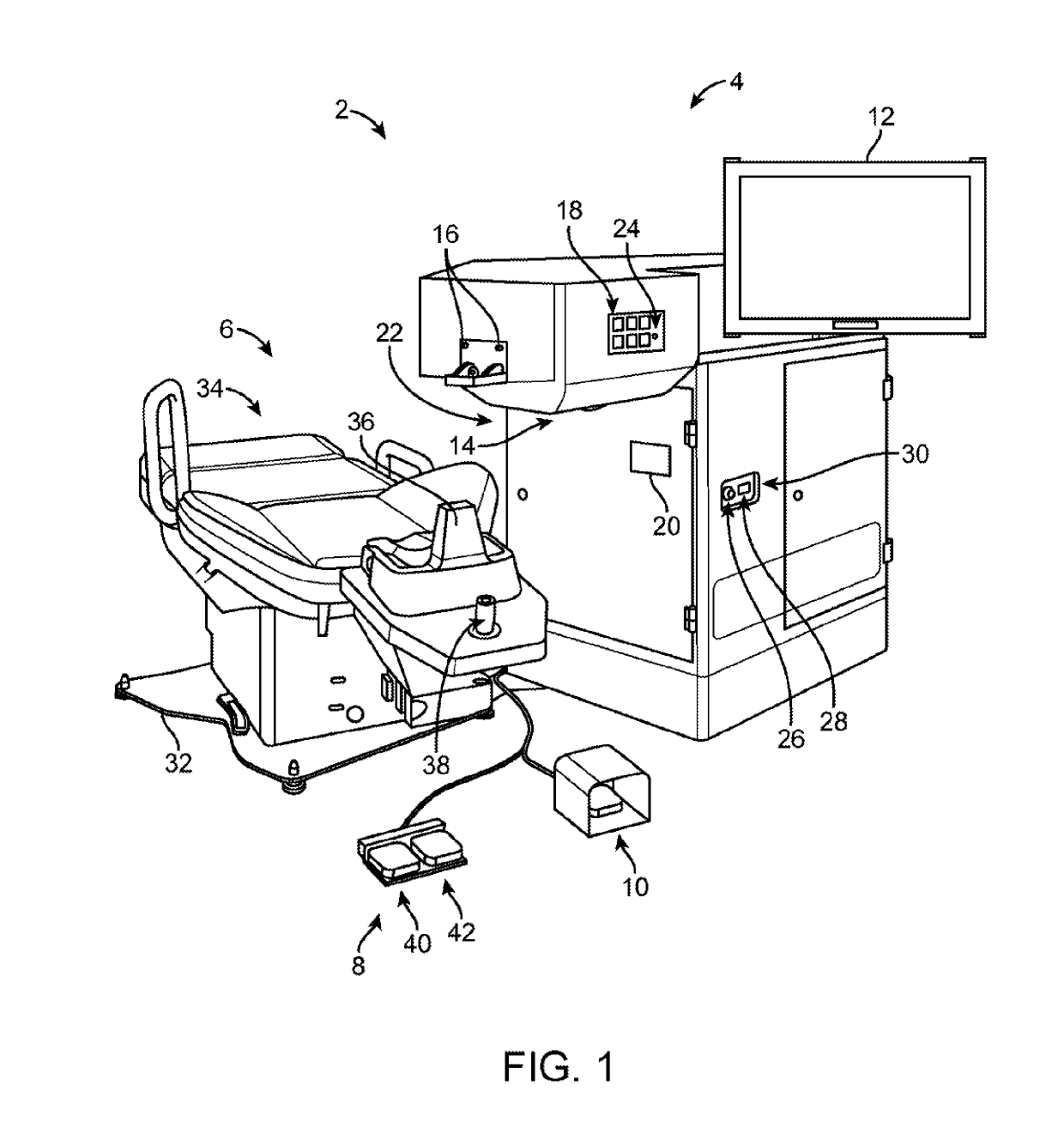
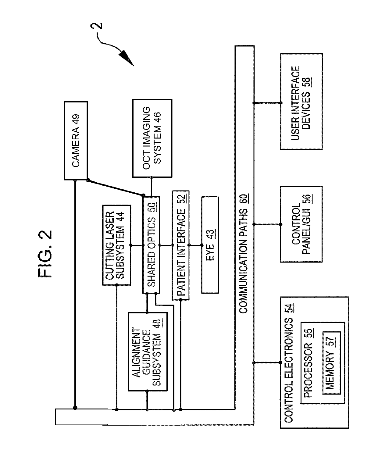
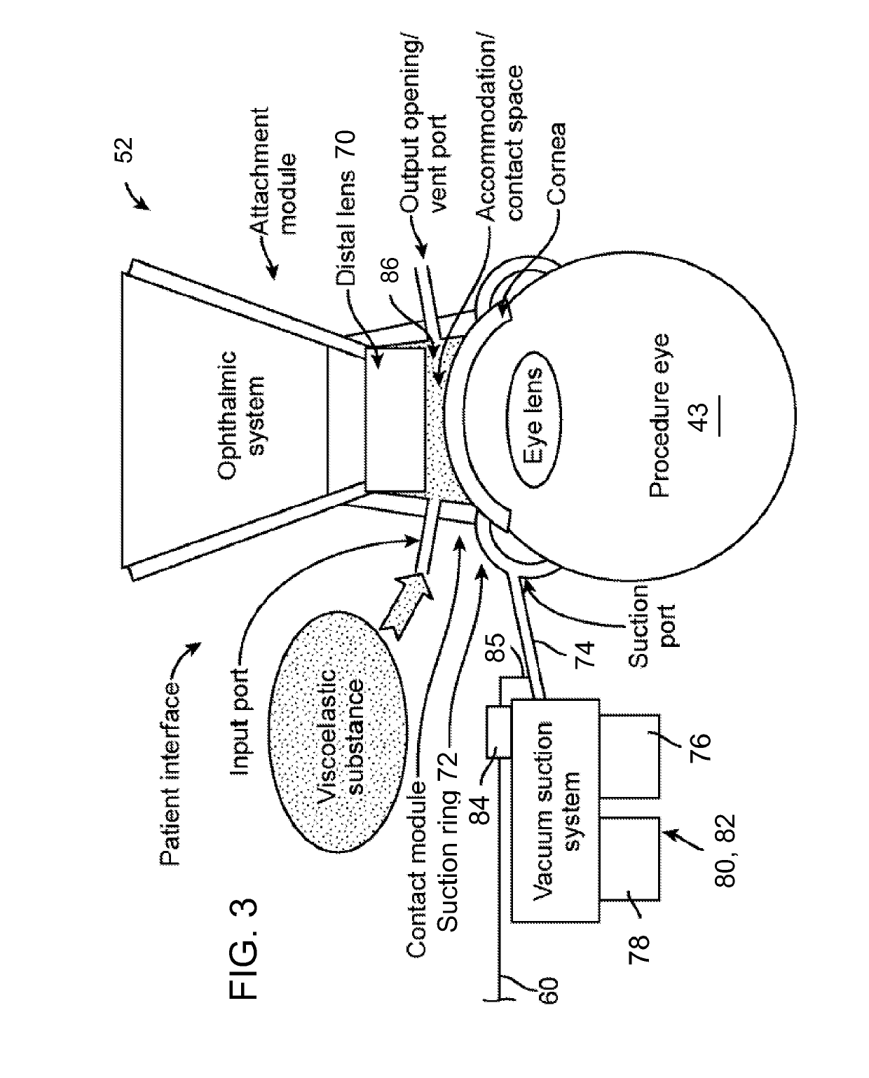
[0021]Methods and systems related to laser eye surgery are disclosed. A laser is used to form precise incisions in the cornea, in the lens capsule, and / or in the crystalline lens nucleus. In a preferred embodiment, a laser eye surgery system includes a laser cutting subsystem to produce a laser pulse treatment beam to incise tissue within the eye, a ranging subsystem to measure the spatial disposition of external and internal structures of the eye in which incisions can be formed, an alignment subsystem, and shared optics operable to scan the treatment beam, a ranging subsystem beam, and / or an alignment beam relative to the laser eye surgery system. The alignment subsystem can include a video subsystem that can be used to, for example, provide images of the eye during docking of the eye to the laser eye surgery system and also provide images of the eye once the docking process is complete. In a preferred embodiment, a liquid interface is used between a patient interface lens and the...


PUM


Abstract

A laser eye surgery system that has a patient interface between the eye and the laser system relying on suction to hold the interface to the eye. The patient interface may be a liquid-filled interface, with liquid used as a transmission medium for the laser. During a laser procedure various inputs are monitored to detect a leak. The inputs may include a video feed of the eye looking for air bubbles in the liquid medium, the force sensors on the patient interface that detect patient movement, and vacuum sensors directly sensing the level of suction between the patient interface and the eye. The method may include combining three monitoring activities with a Bayesian algorithm that computes the probabilities of an imminent vacuum loss event.

Description

RELATED APPLICATION[0001]This application is a non-provisional application and claims the benefit under 35 U.S.C. § 119(e) of U.S. Provisional Application Ser. No. 62 / 065,481, filed Oct. 17, 2014, which is incorporated herein in its entirety as if fully set forth.FIELD OF THE INVENTION[0002]The present application pertains to laser-assisted eye surgery using a vacuum-held optical interface and, more particularly, to systems and methods for monitoring and reacting to insufficient vacuum within the interface.BACKGROUND[0003]A cataract is formed by opacification of the crystalline lens or its envelope—the lens capsule—of the eye. The cataract obstructs passage of light through the lens. A cataract can vary in degree from slight to complete opacity. Early in the development of an age-related cataract, the power of the lens may be increased, causing near-sightedness (myopia). Gradual yellowing and opacification of the lens may reduce the perception of blue colors as those wavelengths are...

Claims


Application Information

Patent Timeline
Patent Type & Authority Applications(United States)
IPC IPC(8): A61F9/009
CPCA61F9/009A61F2009/00887A61F2009/00878A61B2217/005A61F2009/00844A61F2009/0052A61F2009/00872
Inventor CAMPOS, MICHAEL A.GONZALEZ, JAVIER G.MILLER-GADDA, TERESA G.
Owner AMO DEVMENT
Why Eureka
Try Eureka