Splatter shield systems and methods for additive manufacturing

a technology of additive manufacturing and shielding, applied in the field of additive manufacturing systems and methods, can solve the problems of increased contamination and inferior mechanical properties, and achieve the effect of reducing the overall inert gas flow

Active Publication Date: 2019-05-23
HAMILTON SUNDSTRAND CORP
View PDF0 Cites 1 Cited by
  • Summary
  • Abstract
  • Description
  • Claims
  • Application Information

AI Technical Summary

Benefits of technology

[0013]The method can include controlling a gap size between build area and the splatter shield. The gap size is controlled to minimize overall inert gas flow, and / or to direct inert gas flow at an interface of a laser beam and powder bed, and / or to flush out particles and / or condensate towards exhaust vents.

Problems solved by technology

However, “dead zones” exist where material gets partially oxidized, resulting in inferior mechanical properties, because of non-uniform gas coverage.
The level of contamination increases with powder reuse / recycling.

Method used


Image

  • Splatter shield systems and methods for additive manufacturing
  • Splatter shield systems and methods for additive manufacturing
  • Splatter shield systems and methods for additive manufacturing

Examples


Embodiment Construction

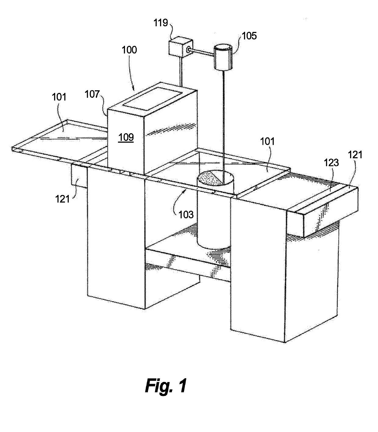
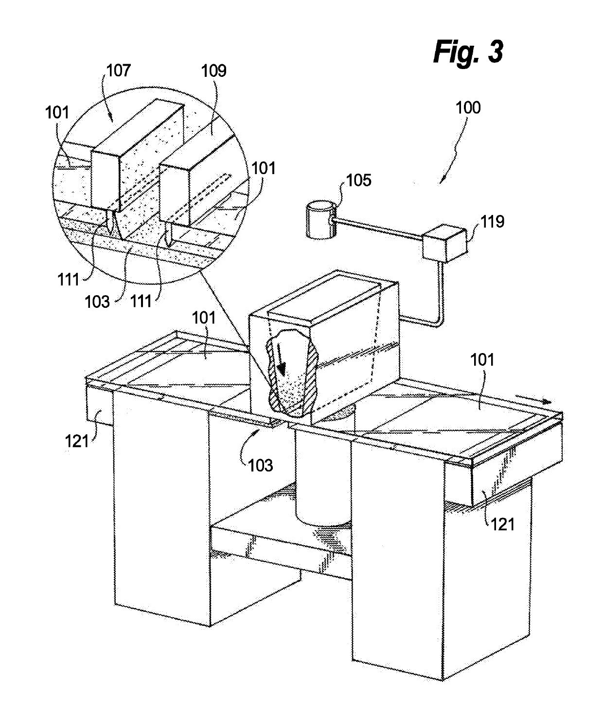
[0020]Reference will now be made to the drawings wherein like reference numerals identify similar structural features or aspects of the subject disclosure. For purposes of explanation and illustration, and not limitation, an illustrative view of an embodiment of a system in accordance with the disclosure is shown in FIG. 1 and is designated generally by reference character 100. Other embodiments and / or aspects of this disclosure are shown in FIGS. 2-4. The systems and methods described herein can be used to enhance environment control and build quality in an additive manufacturing system, for example, or for any other purpose.

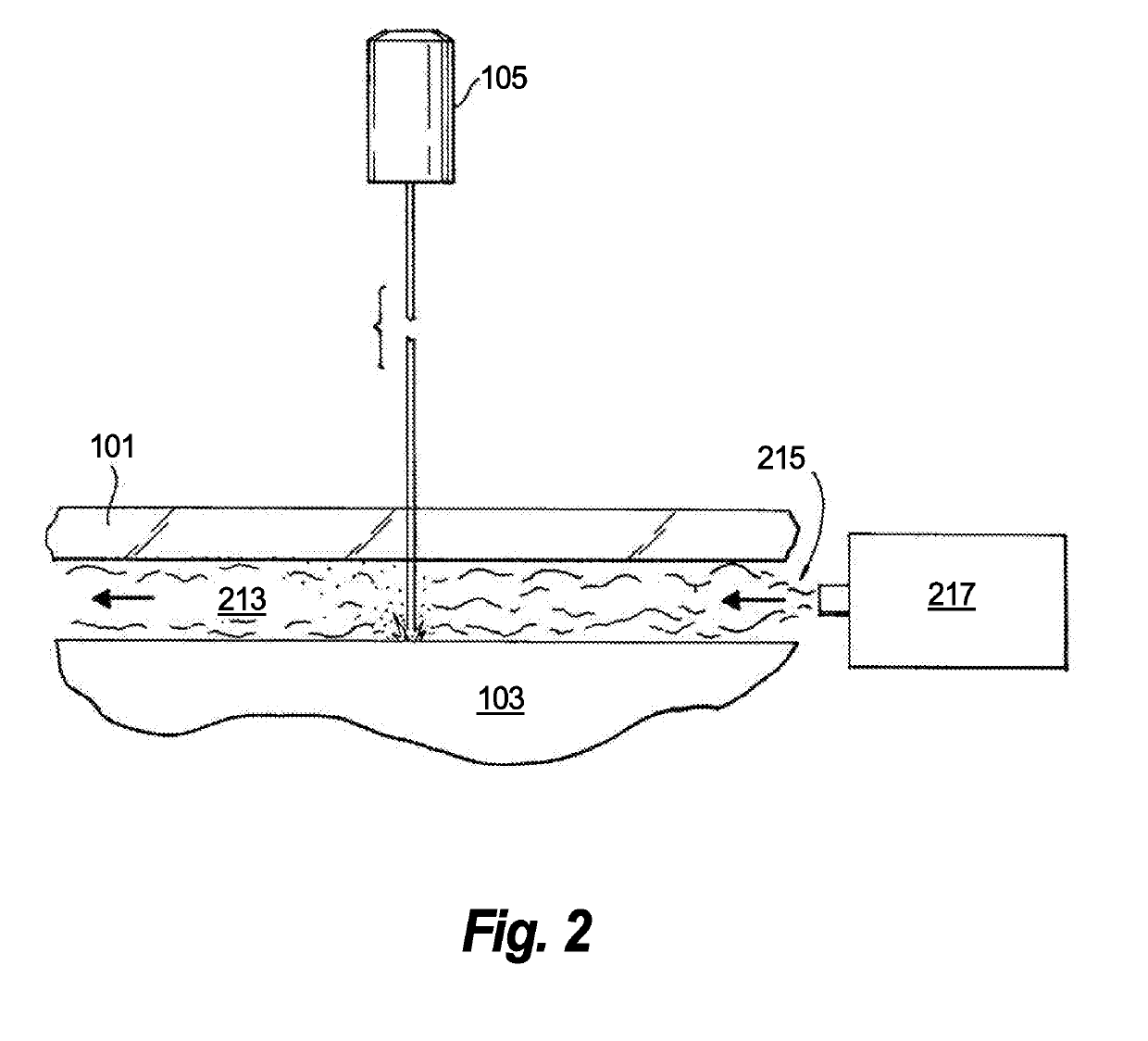
[0021]Referring to FIG. 1, a splatter shield system 100 for an additive manufacturing machine includes one or more splatter shields 101 configured to cover at least a portion of a build area 103 (e.g., a powder bed) during energy application (e.g., as shown in FIG. 1) such that the at least one splatter shield 101 is positioned between an energy source 105 of a...


PUM

PropertyMeasurementUnit
transparentaaaaaaaaaa
shapeaaaaaaaaaa
areaaaaaaaaaaa

Abstract

A splatter shield system for an additive manufacturing machine includes one or more splatter shields configured to cover at least a portion of a build area during energy application such that the at least one splatter shield is positioned between an energy source of an additive manufacturing machine and the build area during energy application. The one or more splatter shields are transparent to an energy source (e.g., a laser) of the additive manufacturing system such that energy application occurs through the splatter shield.

Description

BACKGROUND1. Field[0001]The present disclosure relates to additive manufacturing systems and methods.2. Description of Related Art[0002]During Laser Powder Bed Fusion (LPBF) a shield gas, such as Argon, is utilized to prevent material from oxidation. However, “dead zones” exist where material gets partially oxidized, resulting in inferior mechanical properties, because of non-uniform gas coverage. Also, during manufacturing, an ample amount of metal particles eject at the laser weld pool, become airborne, and get deposited back on top of powder bed along with product of metal evaporation (aka condensate). Chemical composition of the ejected particles and condensate exhibits much higher level of impurities than in a virgin powder.[0003]As a result of powder recoating motion, contaminated powder gets spread across the entire build area and fused into parts. The level of contamination increases with powder reuse / recycling.[0004]Such conventional methods and systems have generally been ...

Claims


Application Information

Patent Timeline
Patent Type & Authority Applications(United States)
IPC IPC(8): B22F3/105B33Y30/00B33Y40/00B33Y50/02
CPCB22F3/1055B33Y30/00B33Y40/00B33Y50/02B22F2003/1059B22F2003/1057B22F2201/10B33Y10/00B23K26/342B29C64/153B29C64/35Y02P10/25B22F10/73B22F10/322B22F12/67B22F12/70B22F12/52B22F10/28B22F10/32B22F12/63B22F10/00
Inventor MIRONETS, SERGEYMADINGER, ALEXANDERGIULIETTI, DIANANOVIKOV, DMITRI
Owner HAMILTON SUNDSTRAND CORP
Why Eureka
Try Eureka