
Rim for non-pneumatic tire and wheel including the same

a non-pneumatic tire and rim technology, which is applied in the field of wheels for non-pneumatic tires, can solve the problems of poor ride comfort, difficult to stably maintain the combination of a non-pneumatic tire and a rim during high-speed driving, and persist in safety issues, so as to achieve the effect of convenient removal

Active Publication Date: 2019-05-23
KUMHO TIRE CO INC
View PDF0 Cites 13 Cited by
  • Summary
  • Abstract
  • Description
  • Claims
  • Application Information

AI Technical Summary

Benefits of technology

Technical effects: The present invention provides a rim that can stably fix a non-pneumatic tire, and also allows for easy removal of the tire when replacing it. This improves the efficiency and convenience of replacing non-pneumatic tires.

Problems solved by technology

However, when a pneumatic tire has insufficient internal air pressure, it has difficulty supporting a vehicle load and absorbing impact from the ground, resulting in poor ride comfort.
However, even if a pneumatic tire is maintained regularly, safety issues persist because it is not possible to prevent damage caused by impact or puncture that may occur during driving.
However, it is difficult to stably maintain the combination of a non-pneumatic tire and a rim during high-speed driving.
Further, when a high rotation force is applied to a wheel, a non-pneumatic tire slips or separates from the rim due to centrifugal force and does not stay fixed to the rim.
Accordingly, a non-pneumatic tire does not transmit a rotation force generated from the axle to the ground and may be displaced from the rim, which results in an accident.
On the other hand, when an adhesive is excessively applied between a non-pneumatic tire and a rim, it is difficult to remove the non-pneumatic tire from the rim due to excessive adhesion, which makes it difficult to replace the non-pneumatic tire.

Method used


Image

  • Rim for non-pneumatic tire and wheel including the same
  • Rim for non-pneumatic tire and wheel including the same
  • Rim for non-pneumatic tire and wheel including the same

Examples


first embodiment

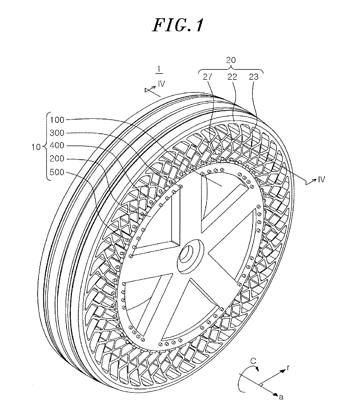
[0039]Referring to FIG. 1, a wheel 1 may include a rim 10 connected to an axle of a vehicle, and a non-pneumatic tire 20 fixed to the rim 10. The non-pneumatic tire 20 is connected to the rim 10 and supports the weight of a vehicle and a live load if any. Further, the non-pneumatic tire 20 can transmit a driving force and a braking force to the road while driving, and absorb or reduce the impact transmitted from the road. Hereinafter, the rim 10 according to the present disclosure and the wheel including the rim will be described with reference to FIGS. 1 to 4.

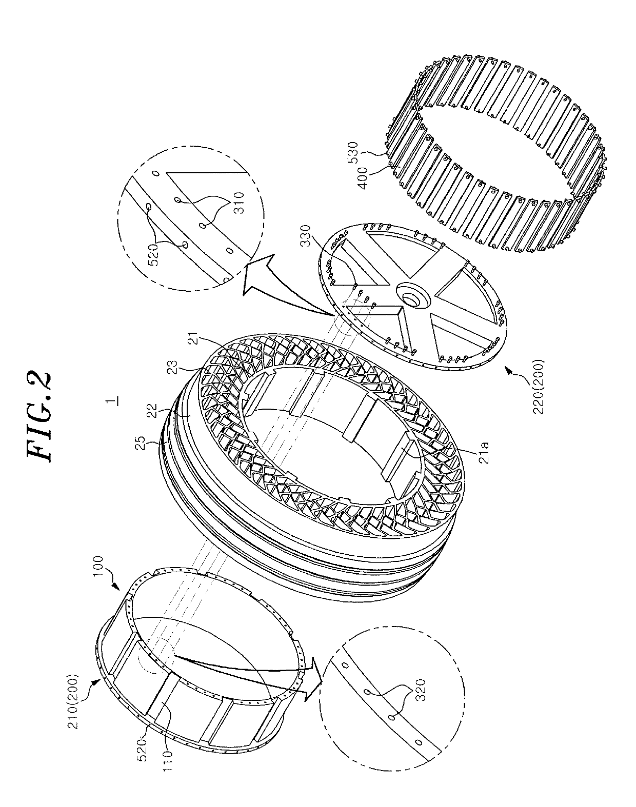
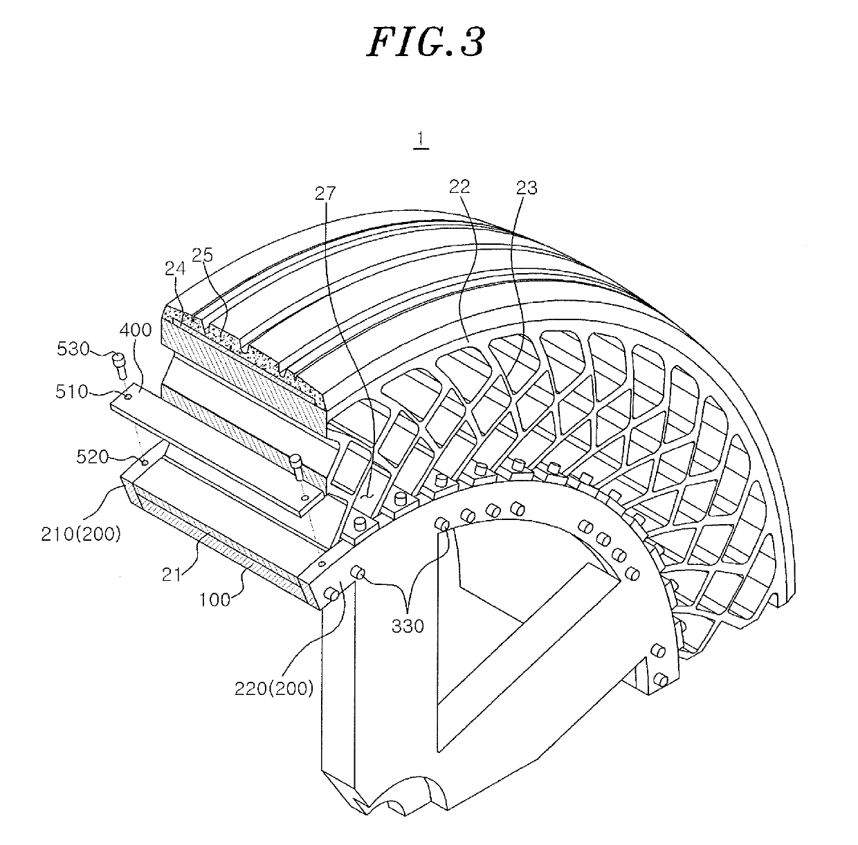
[0040]Referring to FIGS. 1 to 4, the rim 10 may include: a rim wall portion 100 connected to an axle of a vehicle or the like and provided on an inner peripheral side of the non-pneumatic tire; a rim flange portion 200 protruding in a radial direction from the rim wall portion 100; a fastening unit 300 for detachably fixing the rim flange portion 200; a fixing member 400 that is detachably fixed to the rim wall portion 100 and...

second embodiment

[0066]As shown in FIGS. 7 to 10, in accordance with the second embodiment, a hole 201 into which the fixing member 400 is inserted in the axial direction “a” can be formed at the rim flange portion 200 in the axial direction “a.” The hole 201 can be formed at the first rim flange portion 210 and the second rim flange portion 220. Further, the hole 201 may have a shape corresponding to that of the end portion of the fixing member 400 to accommodate the end portion of the fixing member 400. The insertion hole 27 can be formed at the inner band 21 in a shape corresponding to that of the fixing member 400. In other words, the insertion hole 27, the hole 201, and the fixing member 400 may have the same shape when viewed in the axial direction “a.” Therefore, the outer surface of the fixing member 400 is brought into close contact with the inner surface of the hole 201. Accordingly, the non-pneumatic tire 20 can be more stably fixed. Among the holes 201 formed at the first rim flange port...


PUM


Abstract

A rim for a non-pneumatic tire comprises a cylindrical rim wall portion, and a fixing member disposed to be spaced apart from the rim wall portion in a radial direction. The rim wall portion is provided with a fixing protrusion protruding in the radial direction or a fixing groove depressed in the radial direction.

Description

CROSS-REFERENCE TO RELATED APPLICATIONS[0001]This application is based on and claims priority from Korean Patent Application No. 10-2017-0115965, filed on Sep. 11, 2017, the disclosure of which is incorporated herein in its entirety by reference for all purposes.FIELD OF THE INVENTION[0002]The present disclosure relates to a wheel for a non-pneumatic tire that prevents the non-pneumatic tire from slipping and separating from a surface of a rim.BACKGROUND OF THE INVENTION[0003]General vehicle tires are classified into several types based on their structures. Most tires for passenger vehicles are radial tires. A radial tire is attached to a rim connected to an axle of a general vehicle, injected with air at an appropriate air pressure, and then used for driving. However, when a pneumatic tire has insufficient internal air pressure, it has difficulty supporting a vehicle load and absorbing impact from the ground, resulting in poor ride comfort. Therefore, a pneumatic tire needs to be m...

Claims


Application Information

Patent Timeline
Patent Type & Authority Applications(United States)
IPC IPC(8): B60B23/10B60B25/04B60B25/20B60C7/26
CPCB60B23/10B60B25/045B60B25/20B60C7/26B60C2200/04B60B2320/10B60B2900/523B60C7/143B60C7/24B60C7/107B60B23/08B60C7/14B60C7/146B60B25/04
Inventor HWANG, SOON WOOKKIM, KEE WOONKWARK, CHUL WOOSHIN, GWI SEONGPARK, CHANG JUNG
Owner KUMHO TIRE CO INC
Learn More