
First-stage turbine vane supporting structure and gas turbine including same

a supporting structure and turbine vane technology, applied in the field of gas turbines, can solve the problems of reducing the operational amplitude reducing the efficiency of the reciprocating mechanism, and reducing the operating amplitude, so as to reduce or prevent the flow of chordal leakage and improve the performance of the gas turbin

Active Publication Date: 2019-05-23
DOOSAN HEAVY IND & CONSTR CO LTD
View PDF7 Cites 3 Cited by
  • Summary
  • Abstract
  • Description
  • Claims
  • Application Information

AI Technical Summary

Benefits of technology

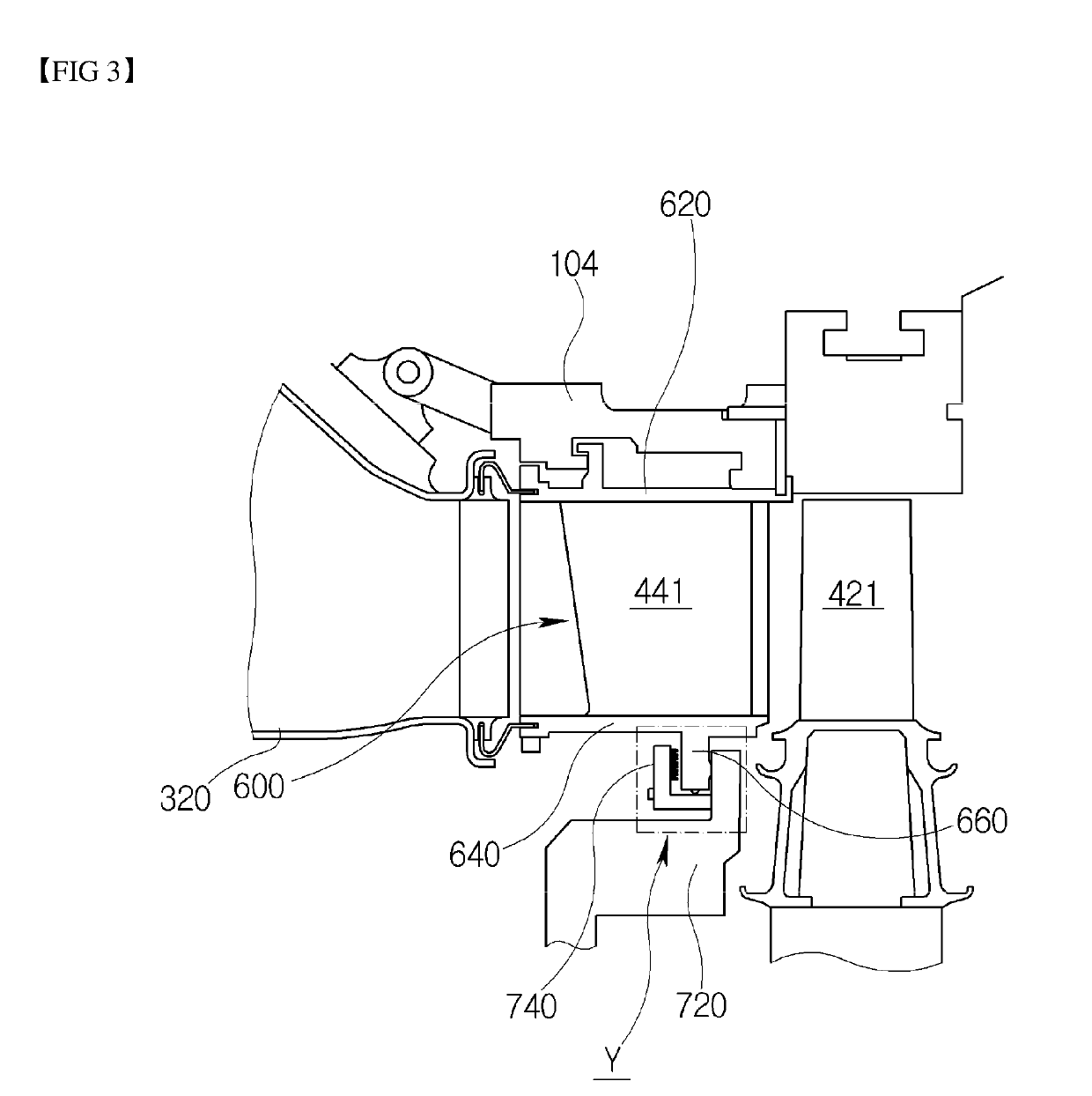
The present invention aims to provide a structure that can reduce the leakage of gas between a turbine vane and its supporting ring in a gas turbine. This is achieved by using a flexible member in a U-shaped space defined by the inner rail, supporting ring, and supporting member. This prevents the formation of gaps and leakage during operation or repair, resulting in improved gas turbine performance.

Problems solved by technology

Therefore, it has no mutually frictional component such as a piston-and-cylinder, thereby consuming an extremely small amount of lubricating oil and reducing the operational amplitude which features the reciprocating mechanism.
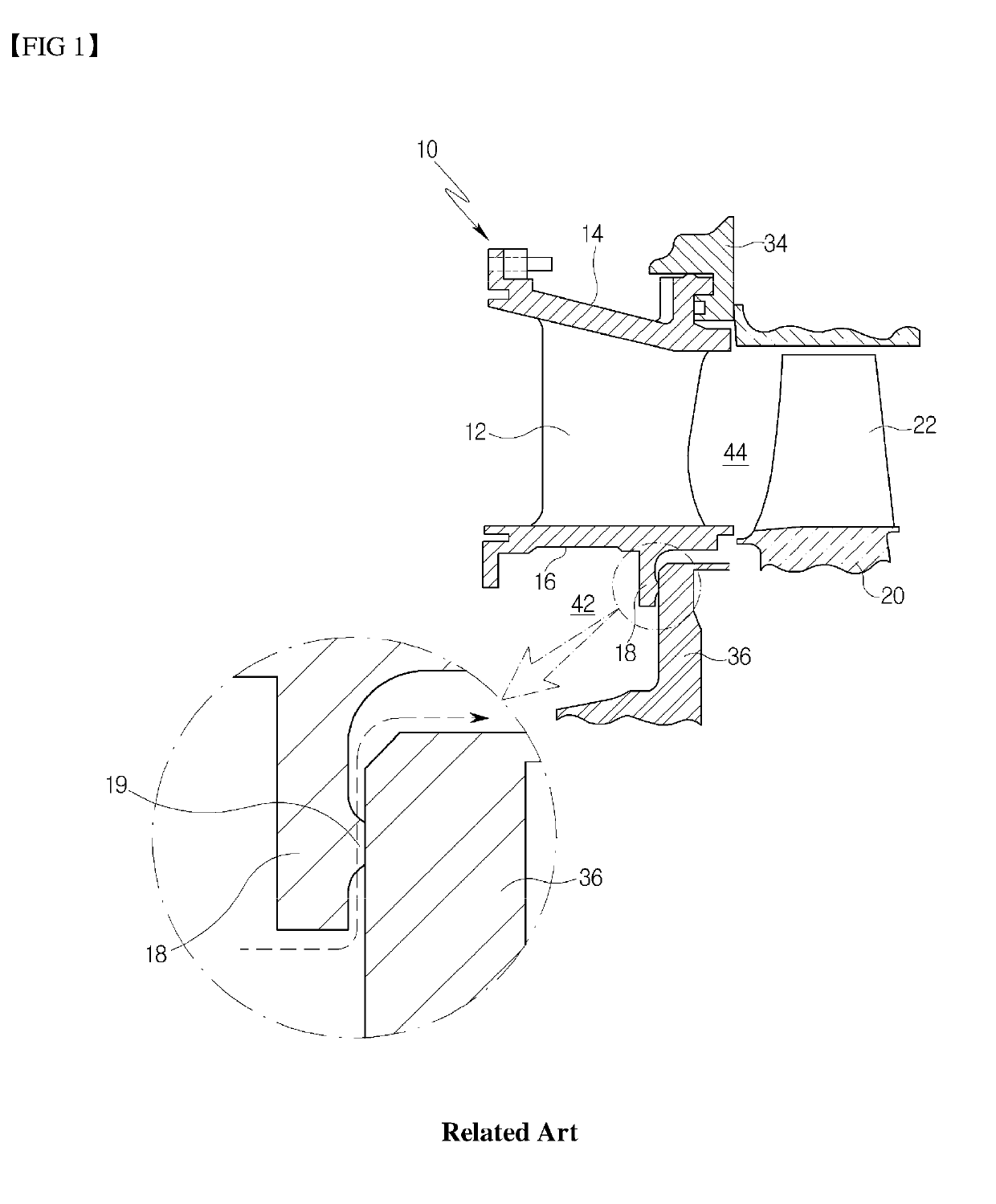
However, a gap is highly likely to occur between the protrusion 19 and the sealing surface of the supporting ring 36 due to the thermal stress of the inner rail 18, which is attributable to the expansion of the vane 12 during the operation of the turbine or due to the warpage of the inner rail occurring during the operation or repair of the turbine.
It is difficult to prevent the flow of chordal leakage when the protrusion 19 fails to be in tight contact with the sealing surface of the supporting ring 36.

Method used


Image

  • First-stage turbine vane supporting structure and gas turbine including same
  • First-stage turbine vane supporting structure and gas turbine including same
  • First-stage turbine vane supporting structure and gas turbine including same

Examples


first embodiment

[0103]Hereinbelow, further embodiments of the present invention will be described. These embodiments are modifications in the structure of the Therefore, only differences of the other embodiments will be described.

[0104]First, as illustrated in FIG. 7, according to a second embodiment of the present invention, instead of the labyrinth seal 742 provided in the first embodiment, a brush seal 744 is provided in the U-shaped space defined by the inner rail 660, the supporting ring 720, and the supporting member 740. The brush seal 744 is preferably positioned closer to the high-pressure region A while being disposed to face the inner rail 660. In the present embodiment, the brush seal 744 is provided between the upstream side surface of the inner rail 660 and the opposing surface of the supporting member 740 and is preferably formed on the supporting member 740.

[0105]However, the invention is not limited to the above configuration. For example, the brush seal 744 may be disposed at a d...

sixth embodiment

[0126]Specifically, in the sixth embodiment, a flexible member 3820 is interposed between a radial end surface of an inner rail 660 and the opposing surface of a supporting member 740. The flexible member 3820 may be composed of a plurality of leaf springs arranged in the radial direction to form a zigzag shape.

[0127]The flexible member 3820 may extend in the circumferential direction of the turbine 400 to form an overall arc shape.

[0128]Among the leaf springs, a leaf spring coupled to the inner rail 660 is provided with a plurality of tapped holes 3822. The flexible member 3820 can be screw-fixed to the inner rail 660 through the threaded holes.

[0129]However, the method of coupling the flexible member to the inner rail 660 is not limited to the above configuration. For example, the inner rail 660 may be provided with an insertion groove and the flexible member 3820 may be inserted into the insertion groove.

[0130]Accordingly, both the outermost leaf springs of the flexible member 38...


PUM


Abstract

A first-stage turbine vane supporting structure reduces chordal leakage between a first-stage turbine vane segment and its supporting ring. The structure includes a first-stage turbine vane segment including an outer platform, an inner platform, and a first-stage turbine vane disposed between the inner and outer platforms; an inner rail protruding from the inner platform in a longitudinal direction of the first-stage turbine vane; a supporting ring for supporting the first-stage turbine vane segment by engaging with the inner rail while facing one surface of the inner rail; a supporting member engaging with the supporting ring to define a U-shaped space bordered by three side surfaces surrounding the inner rail; and a flexible member interposed between the inner rail and one of the three side surfaces of the U-shaped space. A protrusion formed on the inner rail engages with a sealing surface of the supporting ring in an airtight manner.

Description

CROSS REFERENCE TO RELATED APPLICATIONS[0001]The present application claims priority to Korean Patent Application No. 10-2017-0155404, filed Nov. 21, 2017, the entire contents of which is incorporated herein for all purposes by this reference.BACKGROUND OF THE INVENTION1. Field of the Invention[0002]The present invention relates to gas turbines. More particularly, the present invention relates to a first-stage turbine vane supporting structure capable of reducing chordal leakage between a first turbine vane segment and a supporting ring and to a gas turbine including the same.2. Description of the Background Art[0003]In general, a turbine refers to a mechanical device that extracts energy from a fluid, such as water, gas, or vapor, and converts it into useful mechanical work. A turbine is a turbo-machine with at least one moving part called a rotor assembly, which is a shaft with blades or vanes attached, in which a fluid is injected to impact the blades or vanes and cause a reactio...

Claims


Application Information

Patent Timeline
Patent Type & Authority Applications(United States)
IPC IPC(8): F01D11/00F01D9/04F02C7/28F02C3/04
CPCF01D11/005F01D9/041F02C7/28F02C3/04F05D2220/3212F05D2240/12F05D2240/57F05D2240/56F05D2250/183F05D2250/712F01D11/02F01D25/28
Inventor KIM, DONG HWA
Owner DOOSAN HEAVY IND & CONSTR CO LTD
Learn More