System and method for conveying solids

a technology of solids and fluids, applied in the field of solids conveying, can solve the problems of limiting the performance of one or both reactors, affecting the flow rate of solids, so as to reduce or prevent fluid flow

Inactive Publication Date: 2014-01-30
GENERAL ELECTRIC CO
View PDF5 Cites 3 Cited by
  • Summary
  • Abstract
  • Description
  • Claims
  • Application Information

AI Technical Summary

Benefits of technology

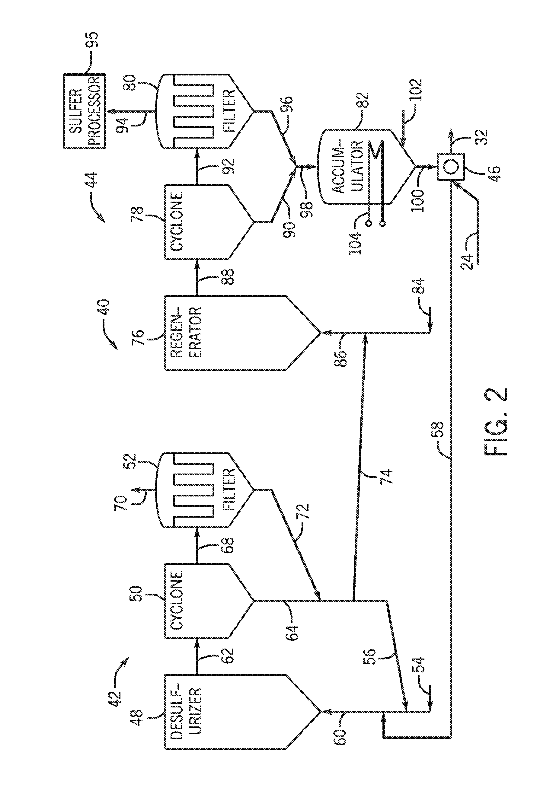
[0004]In a first embodiment, a system includes a desulfurizer configured to receive a gaseous stream. The desulfurizer includes a sulfur absorption material configured to absorb a sulfur compound from the gaseous stream to generate a saturated sulfur absorption material and a product stream substantially free of the sulfur compound. The system also includes a regenerator configured to receive the saturated sulfur absorption material from the desulfurizer. The regenerator is configured to regenerate the saturated sulfur absorption material to generate a regenerated sulfur absorption material and sulfur dioxide. The system also includes a solids pressurizing feeder configured to convey the sulfur absorption material, the saturated sulfur absorption material, or the regenerated sulfur absorption material. The solids pressurizing feeder is configured to at least substantially reduce or prevent fluid flow between the desulfurizer and the regenerator.
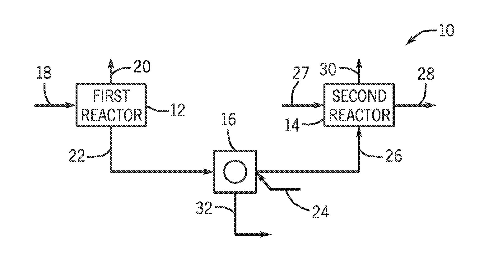
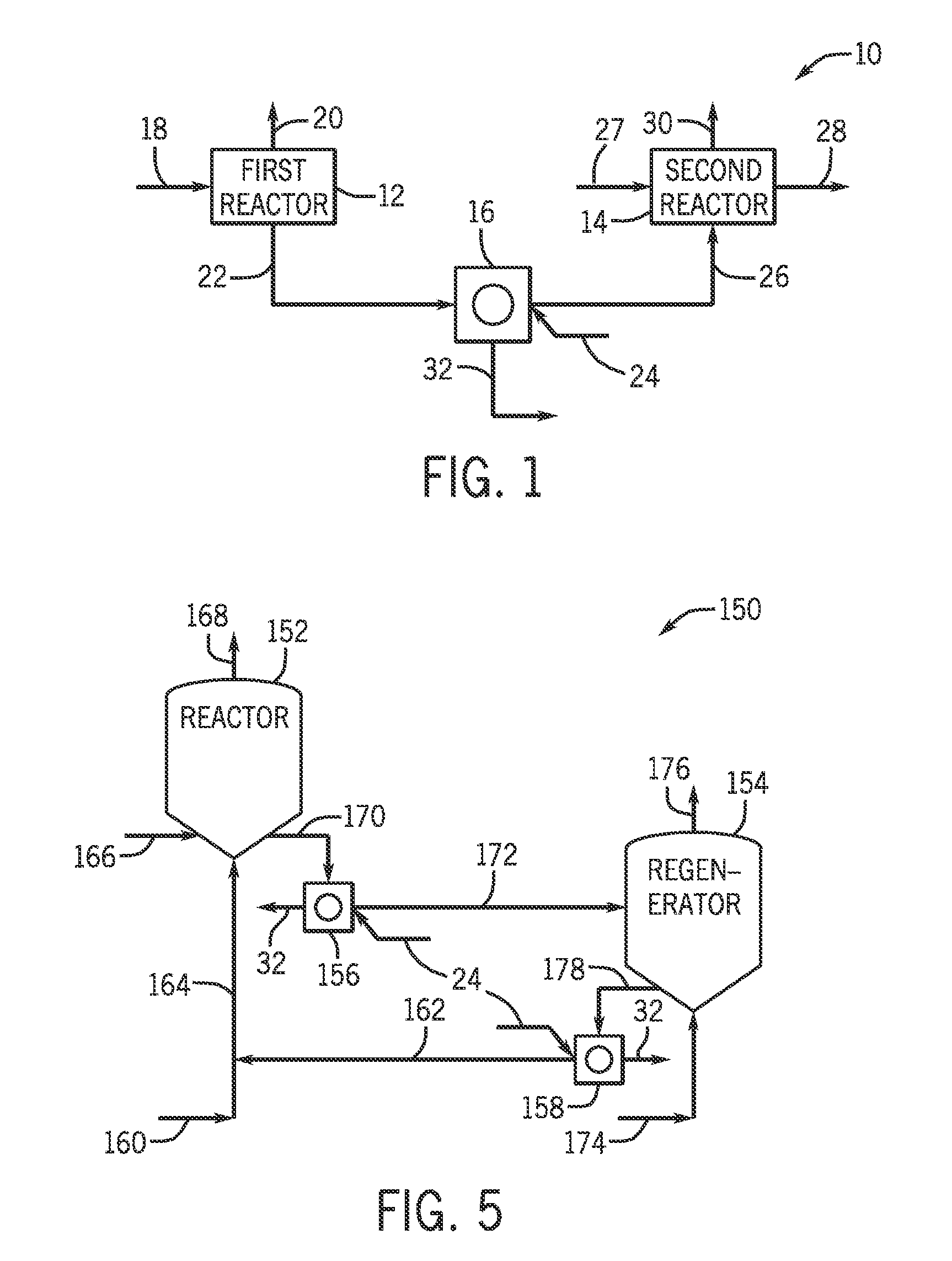
[0005]In a second embodiment, a system includes a first reactor configured to receive a first gaseous stream and generate a first solids stream, a second reactor configured to receive the first solids stream, receive a second gaseous stream, and generate a second solids stream, and a solids pressurizing feeder configured to convey the first solids stream or the second solids stream. The solids pressurizing feeder is configured to at least substantially reduce or prevent fluid flow between the first reactor and the second reactor.
[0006]In a third embodiment, a method includes receiving a first gaseous stream at a first reactor, generating a first solids stream at the first reactor, receiving the first solids stream at a second reactor, receiving a second gaseous stream at the second reactor, generating a second solids stream at the second reactor, conveying the first solids stream or the second solids stream using a solids pressurizing feeder, and substantially reducing or preventing fluid flow between the first reactor and the second reactor using the solids pressurizing feeder.

Problems solved by technology

Unfortunately, it may be difficult to convey solids from one fluidized bed reactor to another without mixing of the fluids between the reactors.
Using these methods of conveying the solids between the coupled beds, the operating pressures of the coupled fluidized bed reactors may be limited to being approximately the same as one another, which may limit the performance of one or both reactors.
Furthermore, any disturbances in pressure or flow rate occurring upstream or downstream of either of the fluidized beds may upset the delicate pressure balance around the system to the point where unwanted flows of solids or fluids or both may occur, and this may lead to unwanted contact and mixing of the contents of the two fluidized beds.

Method used


Image

  • System and method for conveying solids
  • System and method for conveying solids
  • System and method for conveying solids

Examples


Embodiment Construction

[0016]One or more specific embodiments of the present invention will be described below. In an effort to provide a concise description of these embodiments, all features of an actual implementation may not be described in the specification. It should be appreciated that in the development of any such actual implementation, as in any engineering or design project, numerous implementation-specific decisions must be made to achieve the developers' specific goals, such as compliance with system-related and business-related constraints, which may vary from one implementation to another. Moreover, it should be appreciated that such a development effort might be complex and time consuming, but would nevertheless be a routine undertaking of design, fabrication, and manufacture for those of ordinary skill having the benefit of this disclosure.

[0017]When introducing elements of various embodiments of the present invention, the articles “a,”“an,”“the,” and “said” are intended to mean that ther...


PUM

PropertyMeasurementUnit
pressureaaaaaaaaaa
pressuresaaaaaaaaaa
velocitiesaaaaaaaaaa

Abstract

A system includes a first reactor configured to receive a first gaseous stream and generate a first solids stream, a second reactor configured to receive the first solids stream, receive a second gaseous stream, and generate a second solids stream, and a solids pressurizing feeder configured to convey the first solids stream or the second solids stream. The solids pressurizing feeder is configured to at least substantially reduce or prevent fluid flow between the first reactor and the second reactor.

Description

BACKGROUND OF THE INVENTION[0001]The subject matter disclosed herein relates to conveying solids, and, more particularly, to conveying solids in the presence of fluids.[0002]Various industrial processes include the conveying of solids in the presence of fluids, which may be gases or liquids. For example, solids may be conveyed to a fluidized bed reactor in which the fluid is passed through the solid material at high enough velocities to suspend the solid and cause it to behave as if it were a fluid. An integrated gasification combined cycle (IGCC) power plant may include a desulfurization system that uses fluidized bed reactors. A fluid catalytic cracking unit (FCCU) found in many refineries may also include fluidized bed reactors. Two or more fluidized bed reactors may be coupled together in such systems in a manner that allows the solids to circulate continuously between the two or more fluidized bed reactors. In systems such as these, the fluids used in each of the coupled fluidi...

Claims


Application Information

Patent Timeline
Patent Type & Authority Applications(United States)
IPC IPC(8): B01D53/00B01D53/18
CPCB01J8/26C10K1/32C10G11/18C10K1/004B01J8/0045Y02E20/16Y02E20/18B01D53/508B01D53/96B01D2259/128
Inventor LEININGER, THOMAS FREDERICK
Owner GENERAL ELECTRIC CO
Why Eureka
Try Eureka