Rotating module

Active Publication Date: 2019-05-23
SYNCMOLD ENTERPRISE CORP
View PDF4 Cites 3 Cited by
  • Summary
  • Abstract
  • Description
  • Claims
  • Application Information

AI Technical Summary

Benefits of technology

[0008]In one embodiment, a diameter of the pivoting space and a diameter of the cross-section of the pivoting part are both constants, and the diameter of the pivoting space is smaller than the diameter of the cross-section of the pivoting part.
[0009]In one embodiment, the interference between the arcuate arm and the pivoting pa

Problems solved by technology

However, when assembling the conventional supporting device, the interfered level between the rotary unit and the shaft may be designed based on the predetermined weight of the display which is scheduled to be mounted on the supporting device.

Method used


Image

  • Rotating module
  • Rotating module
  • Rotating module

Examples


Example

[0031]Hereafter, examples will be provided to illustrate the embodiments of the present invention. Advantages and effects of the invention will become more apparent from the disclosure of the present invention. It should be noted that these accompanying figures are simplified and illustrative. The quantity, shape and size of components shown in the figures may be modified according to practical conditions, and the arrangement of components may be more complex. Other various aspects also may be practiced or applied in the invention, and various modifications and variations can be made without departing from the spirit of the invention based on various concepts and applications.

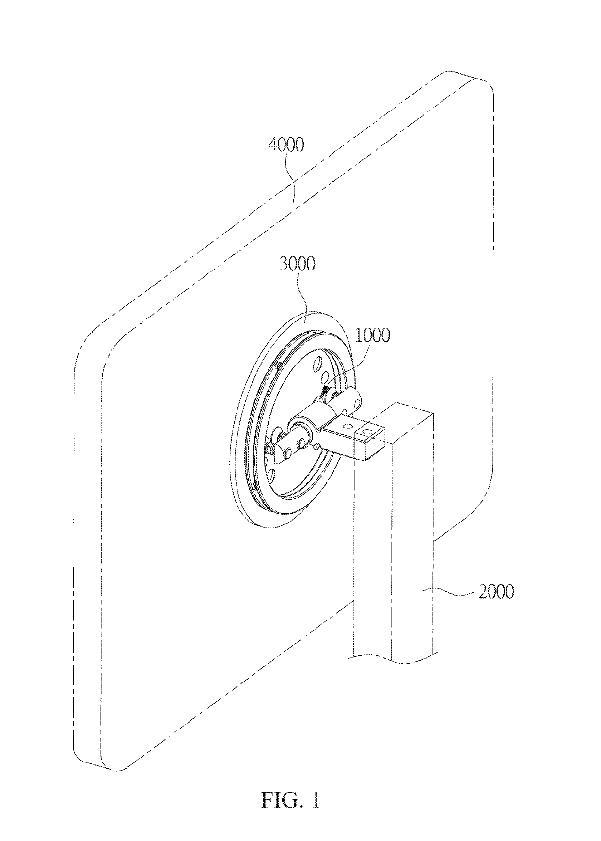
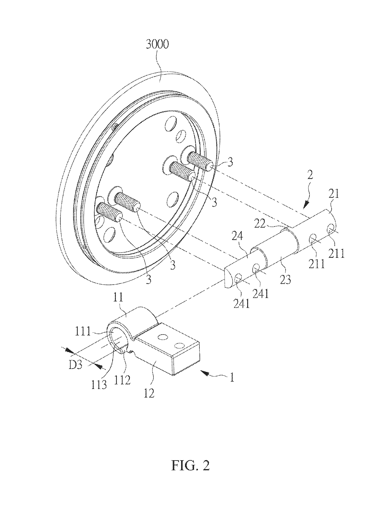
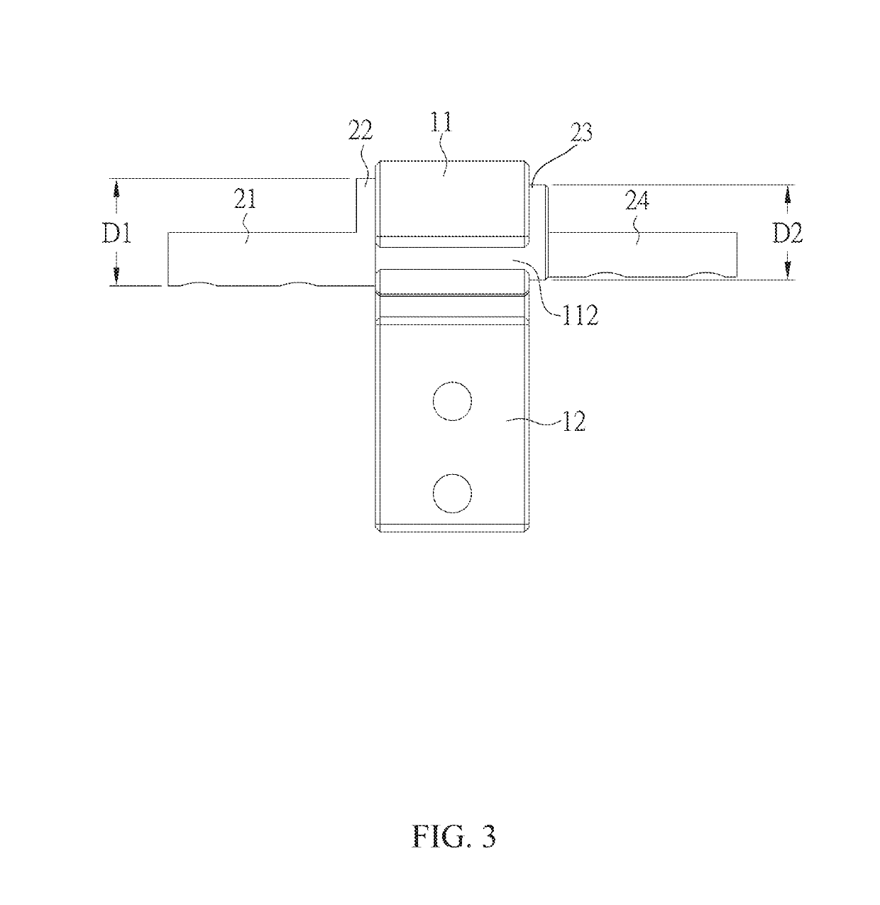
[0032]Please refer to the perspective view of the rotating module 1000 illustrated in FIG. 1, wherein the rotating module 1000 is disposed on an upright 2000, which is disposed on a working surface (not shown in figures), and connecting to a holder 3000 for supporting a display 4000. Please also refer to the ex...


PUM


Abstract

A rotating module comprising a mandrel and at least one rubbing element in provided. The at least one rubbing element is sleeved on the mandrel. The diameter of a pivoting space defined by an arcuate arm of the at least one rubbing element is smaller than the diameter of the mandrel so that the at least one rubbing element and the mandrel are assembled with interference fit.

Description

CROSS REFERENCE TO RELATED APPLICATION[0001]This application claims the benefits of the Taiwan Patent Application Serial Number 106217398, filed on Nov. 23, 2017, and Taiwan Patent Application Serial Number 107203874, filed on Mar. 26, 2018; the disclosures of which are incorporated by reference herein in their entirety.BACKGROUND OF THE INVENTION1. Field of the Invention[0002]The present invention relates to a rotating module. More particularly, the present invention relates to a rotating module applied to a supporting stand.2. Description of Related Art[0003]A conventional supporting device typically includes an upright and a rotating module, wherein the rotating module usually comprises a shaft and a rotary unit being sleeved onto the shaft so that the display may swivel with respect to the upright. In order to stop the display at any swivel angle, there must be some interference between the rotary unit and the shaft.[0004]However, when assembling the conventional supporting devi...

Claims


Application Information

Patent Timeline
IPC IPC(8): F16M11/12F16M11/18
CPCF16M11/126F16M11/18F16M11/08F16M11/10F16M2200/022
Inventor YEH, CHIEN-CHENGYEN, CHING-HUILI, ZE-WEI
Owner SYNCMOLD ENTERPRISE CORP
Why Eureka
Try Eureka