
Devices and methods for determining relative motion

a technology of relative motion and devices, applied in the direction of user-computer interaction input/output, instruments, electric digital data processing, etc., can solve the problems of inconvenient typing of text using touch keyboards, laborious and potentially error-prone tasks, and capacitive-based styluses still far from being ideal solutions

Active Publication Date: 2019-05-23
OTM TECH
View PDF4 Cites 16 Cited by
  • Summary
  • Abstract
  • Description
  • Claims
  • Application Information

AI Technical Summary

Benefits of technology

The patent describes an interferometer that can measure changes in the distance between an interferometer and an object it is observing. This is done by shining a laser beam onto the object and measuring the reflections of that beam using a special detection system. The interferometer can identify the presence of a motion signal when a laser beam moves in relation to the object, and can determine the direction of the motion by measuring the changes in the signals. This technology has applications in various fields such as surface inspection and manufacturing process control.

Problems solved by technology

While smartphones and tablets have built-in touch keyboards in their touchscreen interfaces, the touch keyboards are significantly less convenient than traditional keyboards.
All these limitations make typing text using touch keyboards a laborious and potentially error prone task.
While providing better accuracy than the user's finger, capacitive-based styluses are still far from being an ideal solution since capacitive-based styluses are limited to writing on the same area used for displaying previously-entered text.
Again, the camera-based stylus is limited to specific surfaces.

Method used


Image

  • Devices and methods for determining relative motion
  • Devices and methods for determining relative motion
  • Devices and methods for determining relative motion

Examples


Embodiment Construction

[0046]The following detailed description refers to the accompanying drawings. Wherever possible, the same reference numbers are used in the drawings and the following description to refer to the same or similar parts. The disclosure is not limited to the described embodiments and examples. Instead, the proper scope is defined by the appended claims.

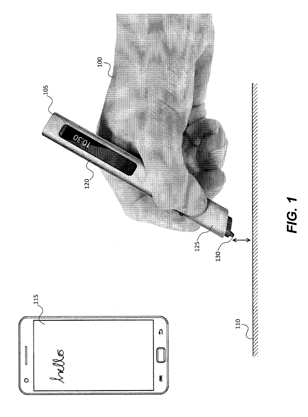
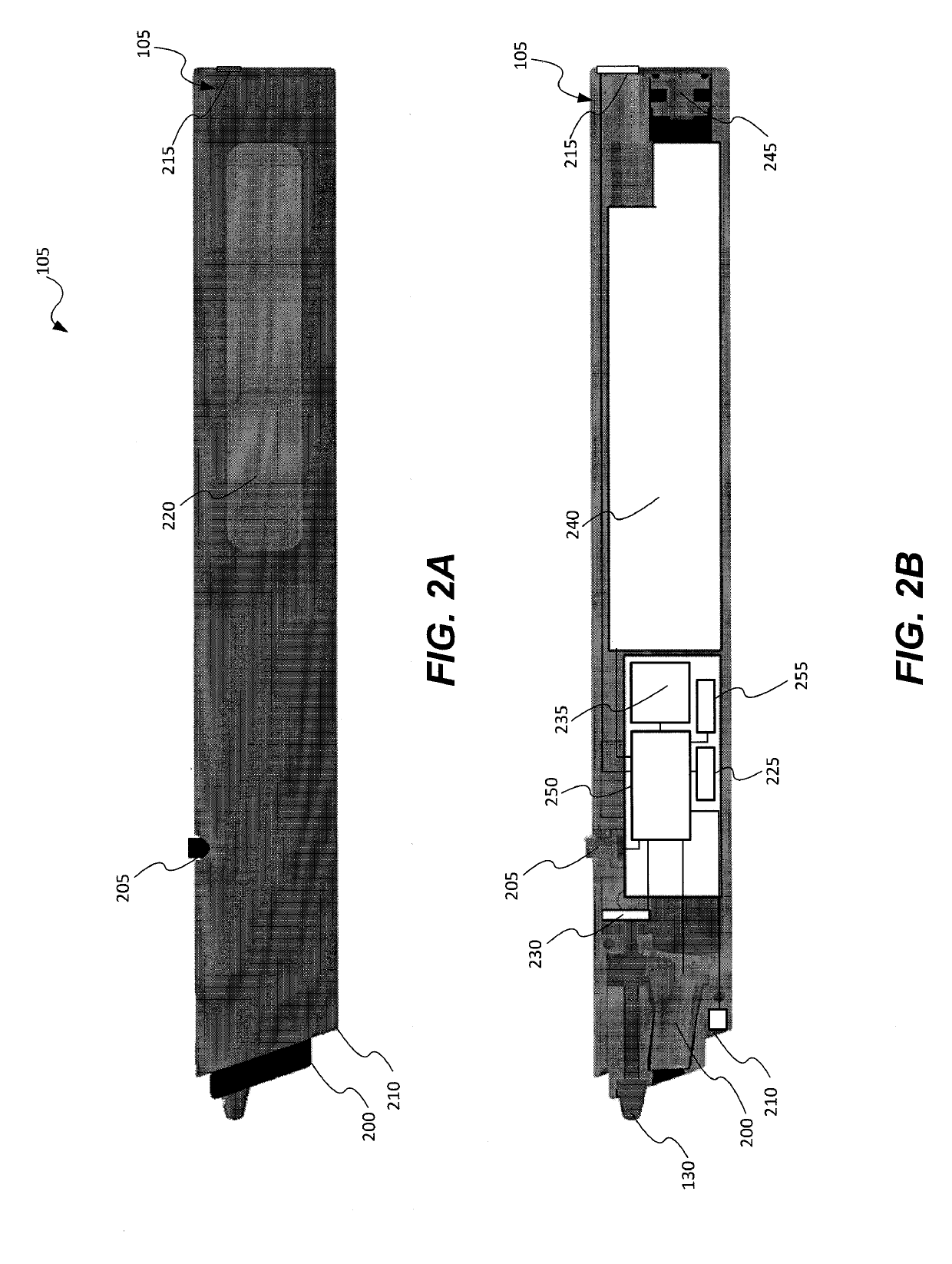
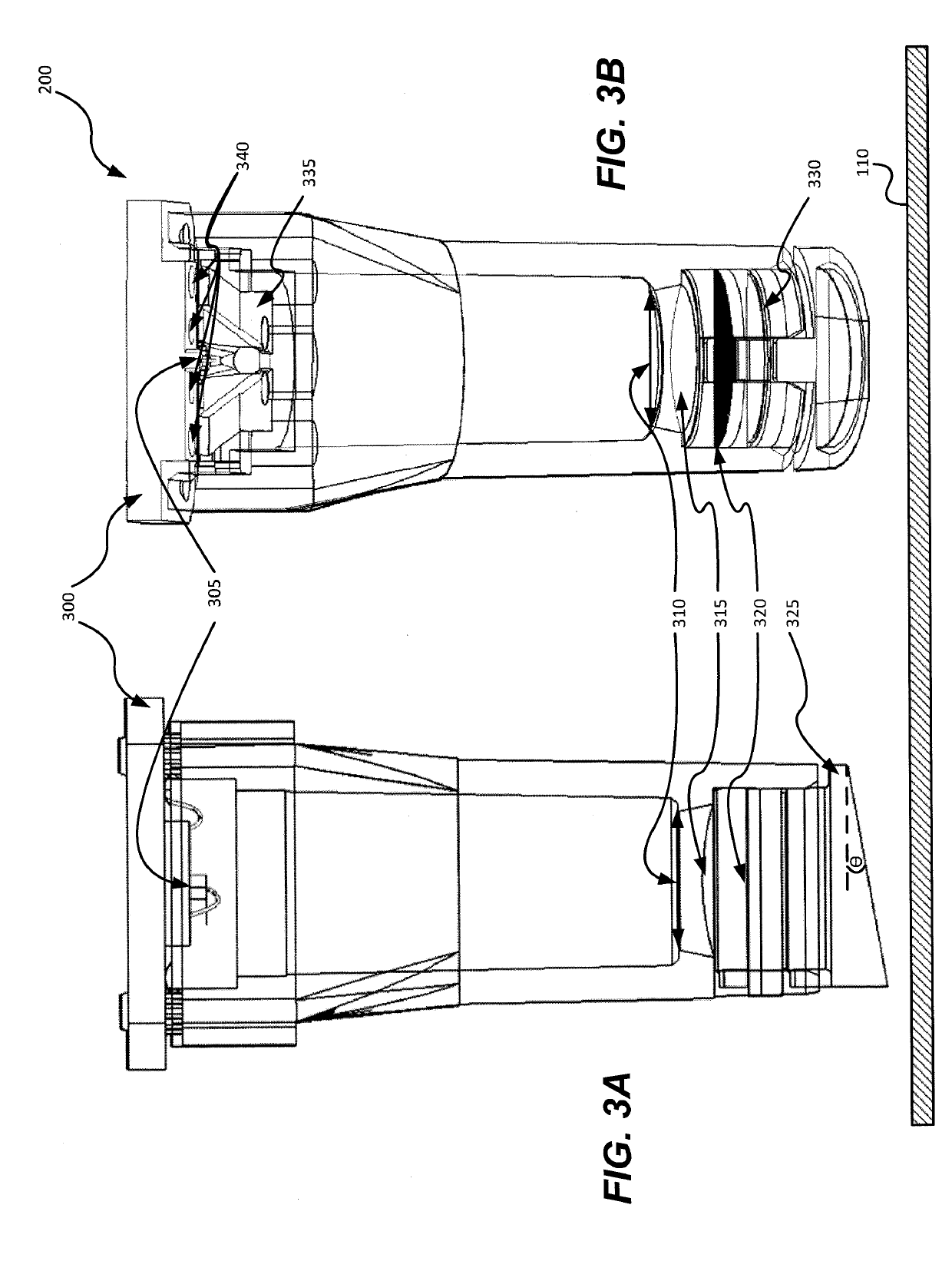
[0047]Disclosed embodiments may involve an interferometer. As used herein, the term “interferometer” broadly includes any device that utilizes the interference of beams of light to determine information. By way of example only, the interferometer may be included in an input device that may be formed in the shape of a pen or pencil, such as, a stylus. The cross section of the input device may be round, square, triangular, rectangular, oval, or any other shape. The width of the input device may be uniform or varied and may have a flattened appearance where a thickness is substantially greater or smaller than the width. The edges of an input...


PUM


Abstract

Devices and methods are disclosed for determining relative motion. In one implementation, an interferometer is provided. The interferometer may include a body, a light source configured to project a coherent light to an opposing surface, a plurality of pairs of light detectors configured to convert reflections of the coherent light into photocurrents, and a processor. The processor may be configured to detect changes in the photocurrents, wherein a first change in the photocurrents, which occurs in response to a relative motion between the body and the opposing surface, represents a motion signal, and a second change in the photocurrents represents a noise signal. The processor may also determine the relative motion between the body and the opposing surface based on the first change in the photocurrents when a ratio between a power of the motion signal and a power of the noise signal is below about 10.

Description

CROSS REFERENCE TO RELATED APPLICATIONS[0001]This application claims the benefit of priority of U.S. Provisional Patent Application No. 62 / 334,784, filed on May 11, 2016, which is incorporated herein by reference in its entirety.BACKGROUNDI. Technical Field[0002]This disclosure generally relates to devices and methods for determining relative motion between an interferometer and an opposing surface.II. Background Information[0003]Smartphone and tablet use has grown rapidly and, in many aspects, these devices have replaced traditional computers (e.g., laptops and PCs). One advantage of traditional computers over smartphones and tablets is ease of text input. While smartphones and tablets have built-in touch keyboards in their touchscreen interfaces, the touch keyboards are significantly less convenient than traditional keyboards. The characters in these touch keyboards are positioned closely together and the user often needs to access different versions of the touch keyboard for spec...

Claims


Application Information

Patent Timeline
Patent Type & Authority Applications(United States)
IPC IPC(8): G06F3/0354G06F3/03G06F3/038G06F3/0488
CPCG06F3/03545G06F3/0304G06F3/0383G06F3/04883
Inventor KINROT, URIKINROT, OPHERBILLAUER, ELI
Owner OTM TECH
Learn More