
Image analysis method, image analysis apparatus, program, learned deep layer learning algorithm manufacturing method and learned deep layer learning algorithm

Active Publication Date: 2019-05-23
NAT CANCER CENT +1
View PDF0 Cites 13 Cited by
  • Summary
  • Abstract
  • Description
  • Claims
  • Application Information

AI Technical Summary

Benefits of technology

The patent text describes a device that can diagnose pathological tissue abnormalities, which can help alleviate the shortage of pathologists and improve their working conditions. The device uses a deep learning algorithm to analyze images of tissue or cells and determine their tumorigenic state. This algorithm is trained using multiple images and data points, resulting in a more accurate and automated diagnosis system.

Problems solved by technology

Although the histopathological diagnosis is performed by a physician, particularly a pathologist, by observing the tissue sample with a microscope or the like to diagnose the tissue sample, in order to be able to perform accurate definitive diagnosis by observing the tissue sample, the pathologist must repeatedly observe tissue samples of various cases under supervision of a highly skilled pathologist, such that the training of a pathologist takes an extraordinary amount of time.
There is a serious pathologist shortage, and as a result of this pathologist shortage, there is a delay in the confirmation of the diagnosis of a patient's malignant tumor, a delay in the start of treatment, or the situation in which treatment is started without waiting for the definitive diagnosis.
Since both normal tissue diagnosis and rapid intraoperative diagnosis both rely on an insufficiently few pathologists, the workload of the individual pathologist becomes enormous and the labor conditions of the pathologist himself also becomes a problem.
However, at present, no solution to this problem has been found.

Method used


Image

  • Image analysis method, image analysis apparatus, program, learned deep layer learning algorithm manufacturing method and learned deep layer learning algorithm
  • Image analysis method, image analysis apparatus, program, learned deep layer learning algorithm manufacturing method and learned deep layer learning algorithm
  • Image analysis method, image analysis apparatus, program, learned deep layer learning algorithm manufacturing method and learned deep layer learning algorithm

Examples


first embodiment

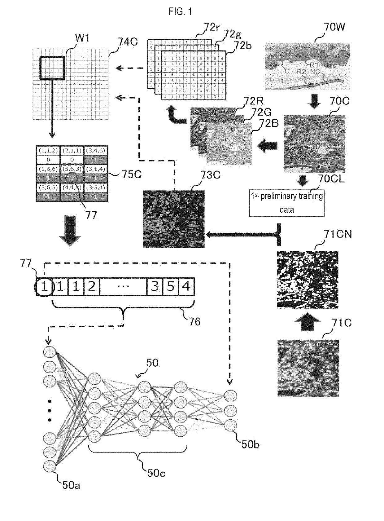
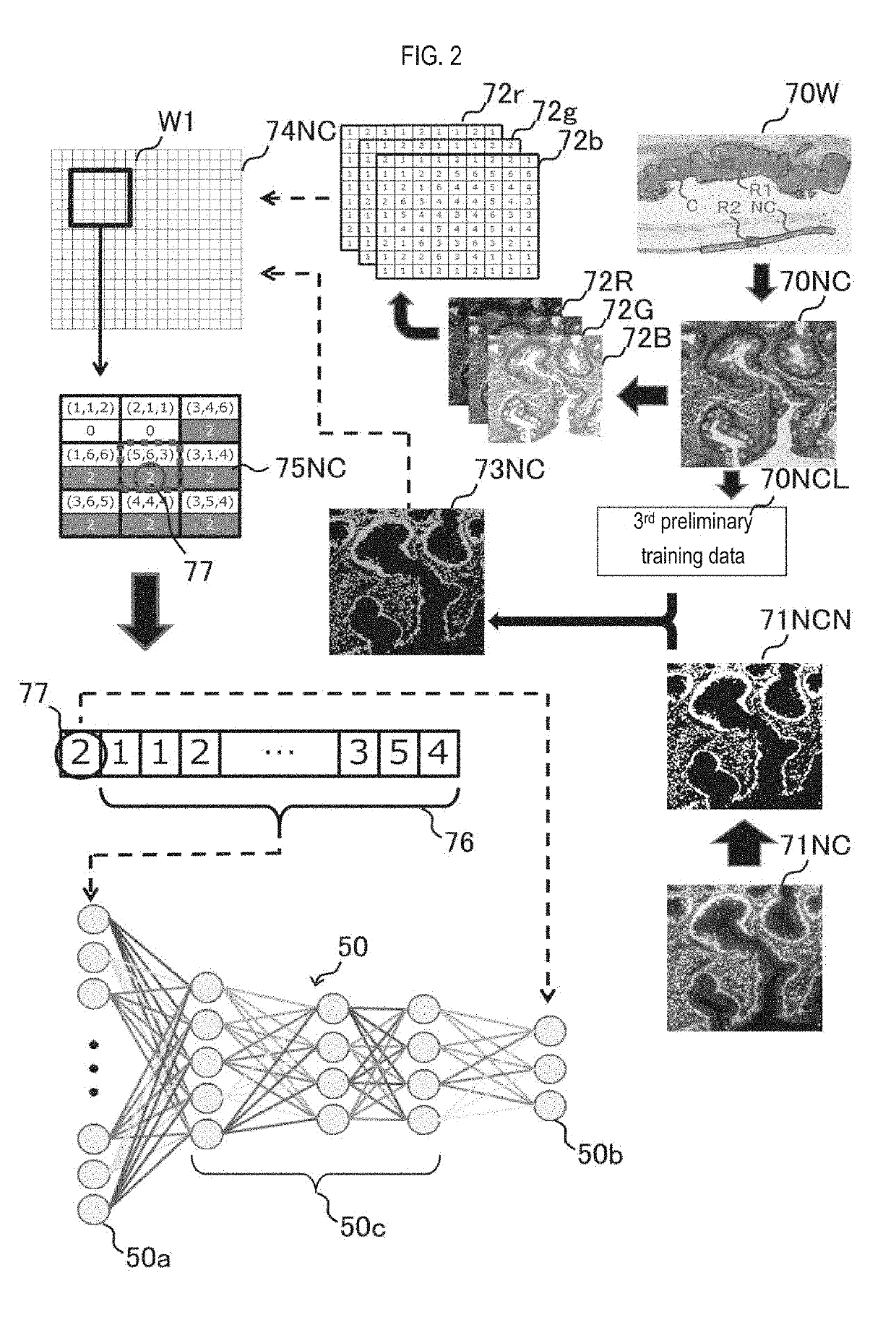
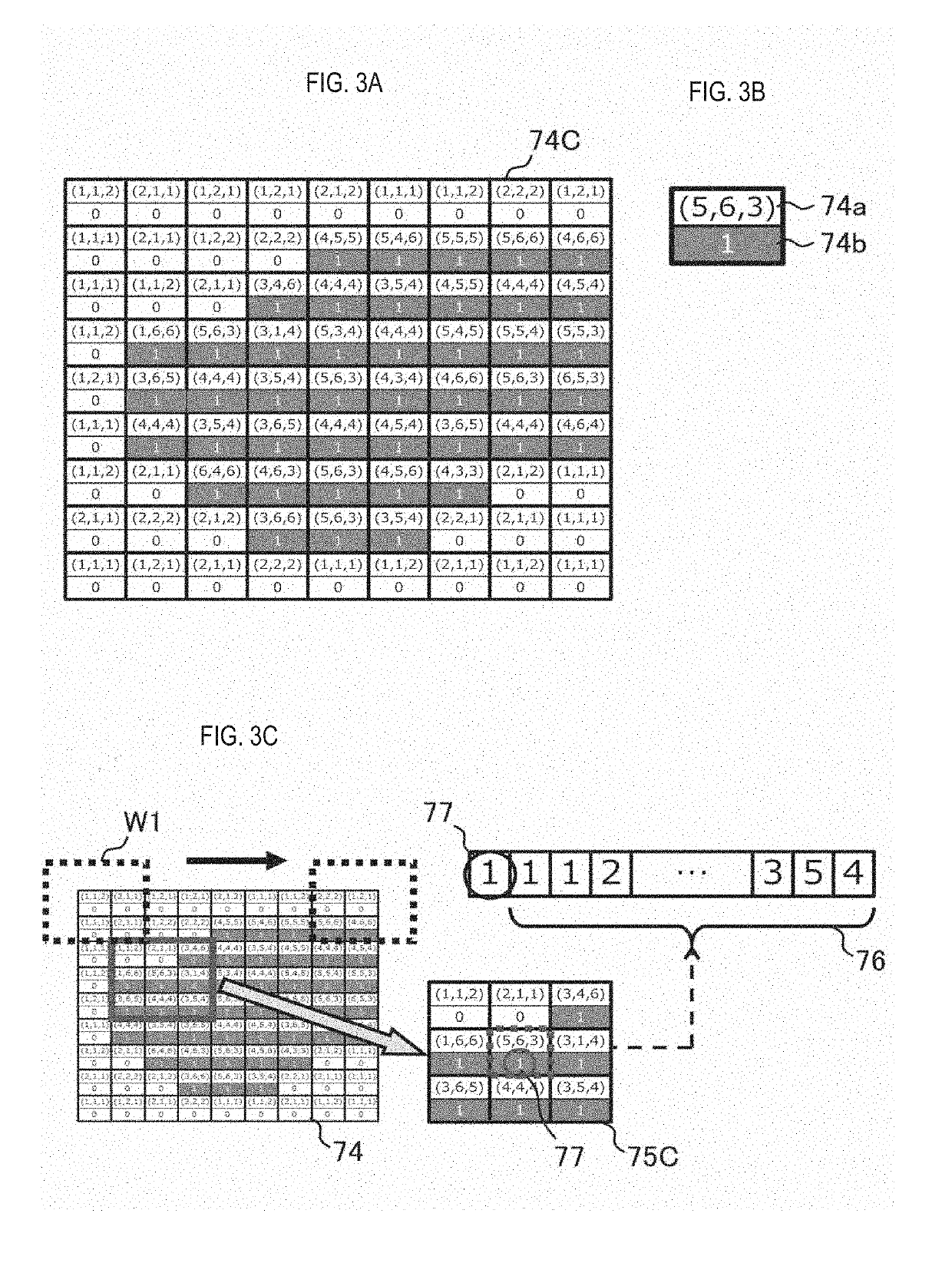
[0114]In the first embodiment, the configuration of a system that implements the deep learning method and image analysis method described in the above outline will be specifically described.

Structure Summary

[0115]Referring to FIG. 6, the image analysis system according to the first embodiment includes a deep learning apparatus 100A and an image analysis apparatus 200A. The vendor side apparatus 100 operates as the deep layer learning apparatus 100A and the user side apparatus 200 operates as the image analysis apparatus 200A. The deep learning apparatus 100A learns using the training data in the neural network 50 and provides the user with a deep learning algorithm 60 that is trained with the training data. The deep learning algorithm configured by the learned neural network 60 is provided from the deep learning apparatus 100A to the image analysis apparatus 200A through a recording medium 98 or a network 99. The image analysis apparatus 200A analyzes an analysis target image using ...

second embodiment

[0193]Hereinafter, the image analysis system according to the second embodiment will be described with respect to points different from the image analysis system according to the first embodiment.

Structure Summary

[0194]Referring to FIG. 14, the image analysis system according to the second embodiment includes a user side apparatus 200, and the user side apparatus 200 operates as an integrated image analysis apparatus 200B. The image analysis apparatus 200B is configured by, for example, a general-purpose computer, and performs both of the deep learning process and the image analysis process described in the first embodiment. That is, the image analysis system according to the second embodiment is a stand-alone system that performs deep learning and image analysis on the user side. The image analysis system according to the second embodiment differs from the image analysis system according to the first embodiment in that the integrated type image analysis apparatus 200B installed on ...

third embodiment

[0203]Hereinafter, the image analysis system according to a third embodiment will be described with respect to points different from the image analysis system according to the second embodiment.

Structure Summary

[0204]Referring to FIG. 16, the image analysis system according to the third embodiment includes a vender side apparatus 100 and a user side apparatus 200. The vendor side apparatus 100 operates as an integrated type image analysis apparatus 100B and the user side apparatus 200 operates as the terminal apparatus 200C. The image analysis apparatus 100B is, for example, a general-purpose computer and is a device on the cloud server side that performs both of the deep layer learning process and the image analysis process described in the first embodiment. The terminal apparatus 200C is composed of, for example, a general-purpose computer, and is a user side terminal apparatus that transmits an analysis target image to the image analysis apparatus 100B via the network 99, and rec...


PUM


Abstract

An image analysis method for generating data indicating a tumorigenic state of an image of a tissue or a cell. The image analysis method is an image analysis method for analyzing an image of a tissue or a cell using a deep learning algorithm of a neural network structure, analysis data are generated from the analysis target image including a tissue or cell to be analyzed, the analysis data are input to the deep learning algorithm, and data indicating the tumorigenic state of tissues or cells in the analysis target image are generated by the depth learning algorithm.

Description

CROSS REFERENCE TO RELATED APPLICATIONS[0001]This application claims priority from prior Japanese Patent Application Publication No. 2017-222166, filed on Nov. 17, 2017, entitled “IMAGE ANALYSIS METHOD, IMAGE ANALYSIS APPARATUS, PROGRAM, LEARNED DEEP LAYER LEARNING ALGORITHM MANUFACTURING METHOD AND LEARNED DEEP LAYER LEARNING ALGORITHM”, the entire contents of which are incorporated herein by reference.FIELD OF THE INVENTION[0002]The present invention relates to an image analysis method, an image analysis apparatus, a program, a method for manufacturing a learned deep layer learning algorithm, and a learned deep layer learning algorithm. More specifically, the present invention relates to an image analysis method, an image analysis apparatus, a program, a method for manufacturing a learned deep layer learning algorithm, and a learned deep layer learning algorithm, which includes generating data indicating a tumorigenic state for an optional position of an image of a tissue or a cel...

Claims


Application Information

Patent Timeline
IPC IPC(8): G06T7/00G06K9/62G06N3/08G06V10/44G06V10/56
CPCG06T7/0012G06K9/6269G06N3/08G06T2207/20084G06T2207/30024G06V20/698G06V10/44G06V10/56G06F18/2411
Inventor YOSHIDA, HIROSHISEKIGUCHI, YOSUKEHAKAMADA, KAZUMIAIHARA, YUKIYAMADA, KOHEIMASUMOTO, KANAKOJAIN, KRUPALI
Owner NAT CANCER CENT
Learn More