Integrated force gauge cable mechanism

Active Publication Date: 2019-05-30
IBM CORP
View PDF12 Cites 0 Cited by
  • Summary
  • Abstract
  • Description
  • Claims
  • Application Information

AI Technical Summary

Benefits of technology

[0005]Aspects of the disclosure generally relate to cables and back shells having integrated force gauges. The force gauge includes a sliding member that engages features such as grooves formed in one or more surfaces of the back shell. The grooves and/or sliding member are sized and shaped such that different forces applied to the sliding member facilitate movement between respective grooves.
[0006]In one aspect, a cable component comprises a back shell having one or more grooves formed in surfaces thereof, and a sliding member coupled to the back shell and positioned adjacent to the one or more grooves. The sliding member has at least one engagement member formed on a surface thereof for engaging the one or more grooves. The sliding member is configured

Problems solved by technology

Often times, cable receptacles, e.g., ports and/or connectors, are located in difficult to reach or difficult to see locations.
However, even if the cable feels or otherwise appears to be properly seated, the cable may

Method used


Image

  • Integrated force gauge cable mechanism
  • Integrated force gauge cable mechanism
  • Integrated force gauge cable mechanism

Examples


Example

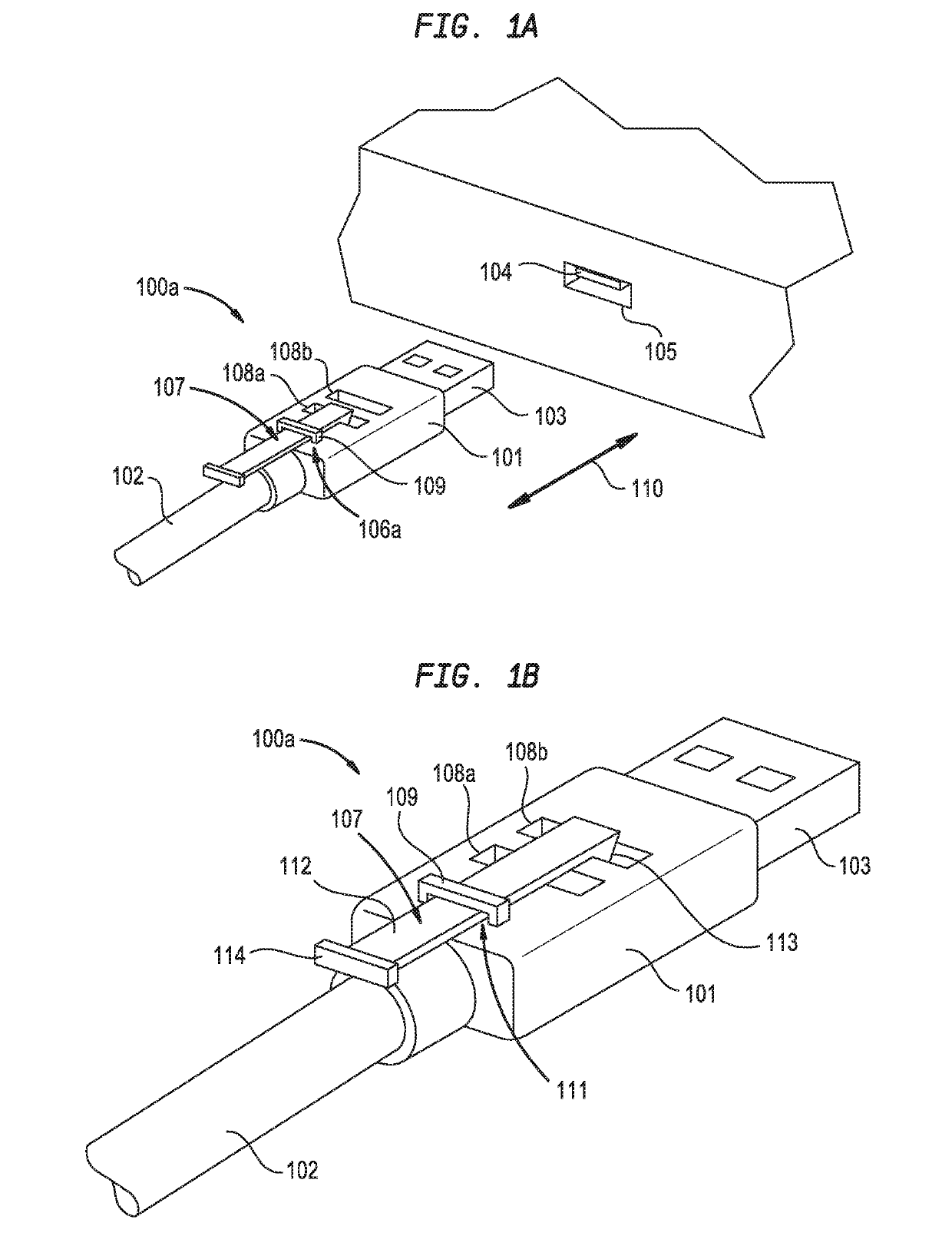
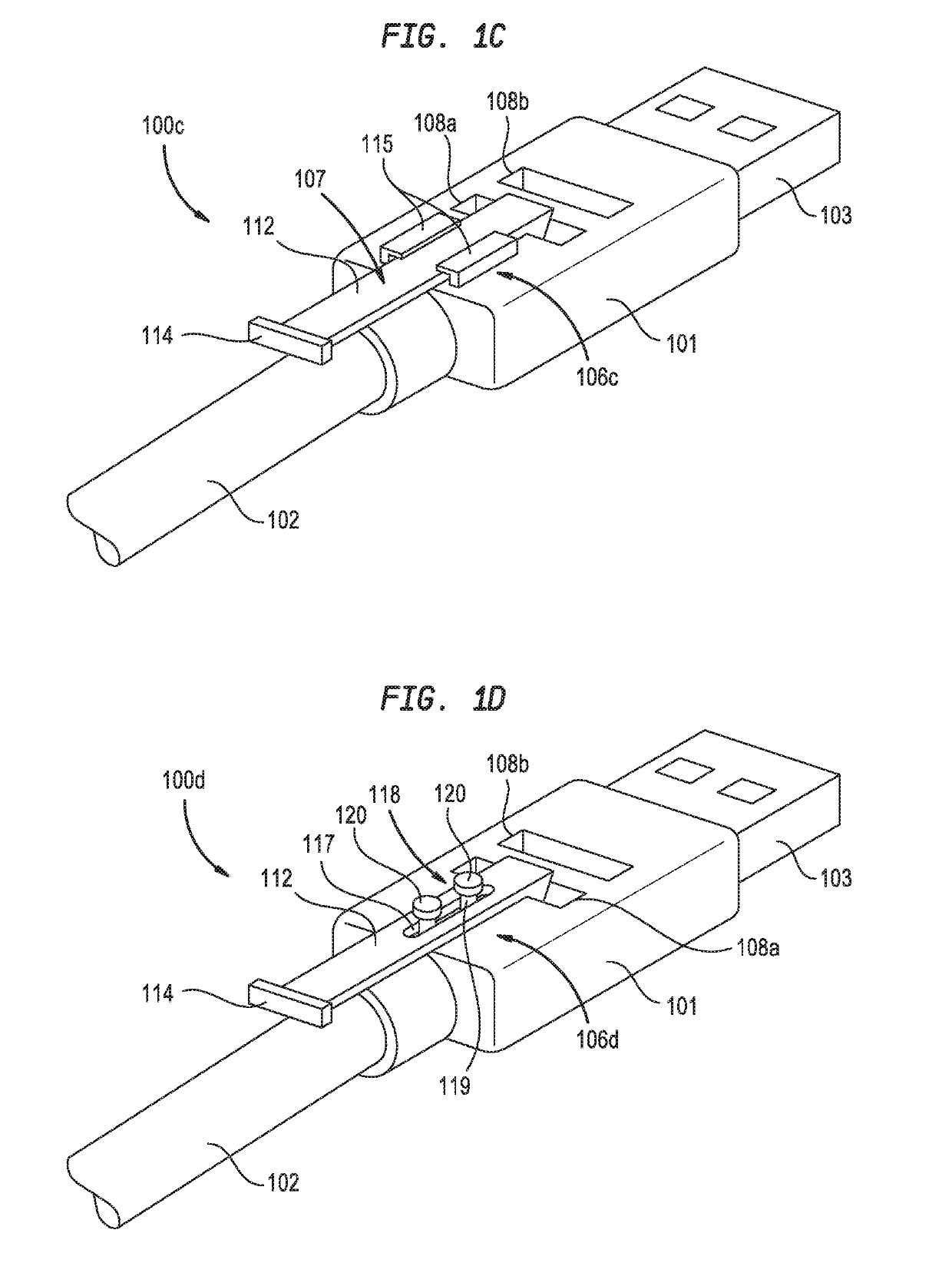
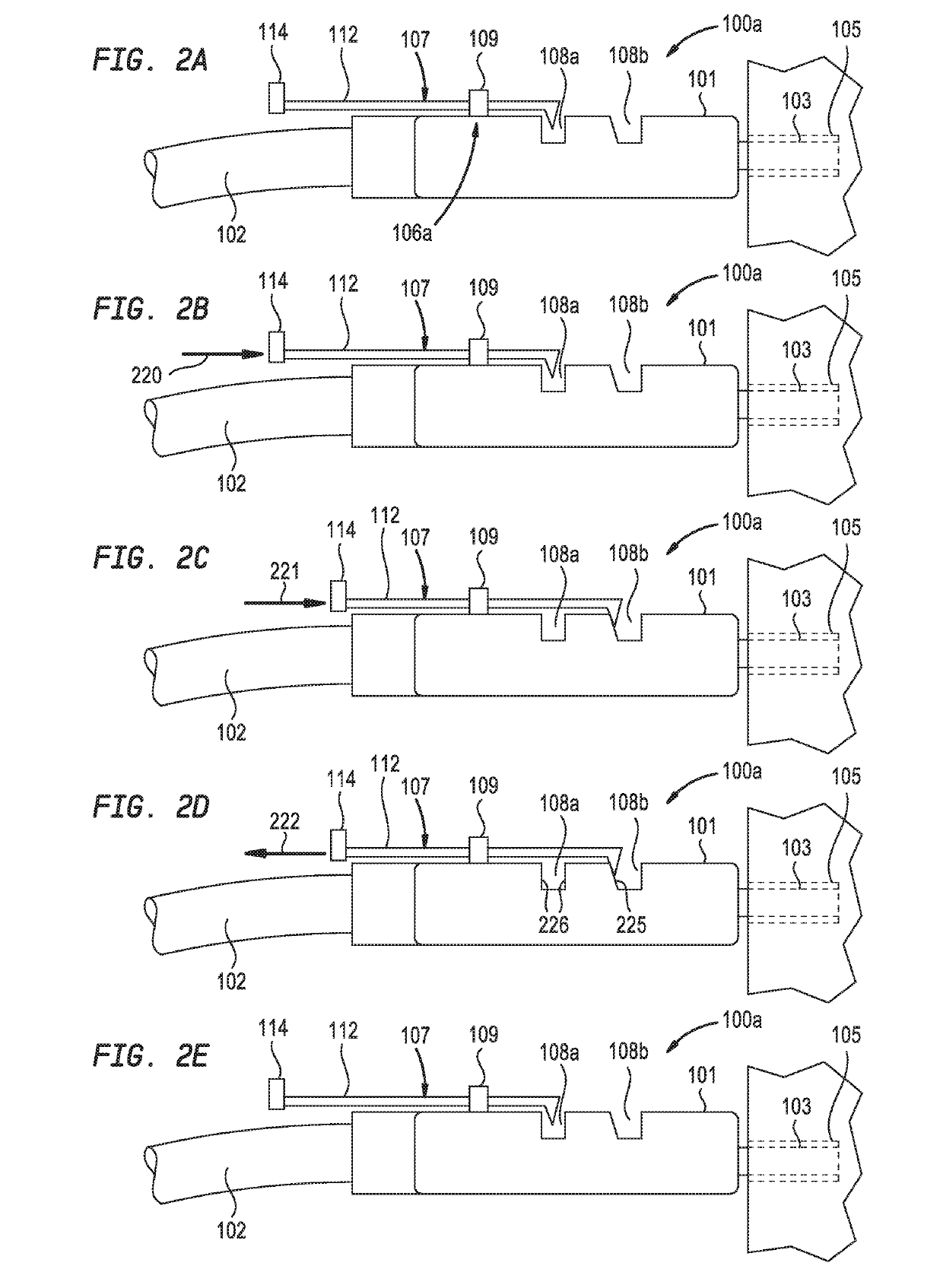
[0016]Aspects of the disclosure generally relate to cables and back shells having integrated force gauges. The force gauge includes a sliding member that engages features such as grooves formed in one or more surfaces of the back shell. The grooves and / or sliding member are sized and shaped such that different forces applied to the sliding member facilitate movement between respective grooves.

[0017]FIG. 1A is a schematic perspective view of a cable 100a and a receptacle 105, according to one aspect of the disclosure. FIG. 1B is an enlarged schematic perspective view of the cable 100a of FIG. 1A, according to one aspect. The cable 100a includes a back shell 101 and a bulk wire 102 coupled to the back shell 101. An electrical connector 103 is coupled to the back shell 101 and is configured to make an electrical connection with a contact 104 located within a receptacle 105. In one example, the receptacle 105 is a port or other connector.

[0018]The back shell 101 is a metal or polymer ho...


PUM


Abstract

Aspects of the disclosure generally relate to cables and back shells having integrated force gauges. The force gauge includes a sliding member that engages features such as grooves formed in one or more surfaces of the back shell. The grooves and/or sliding member are sized and shaped such that a different forces applied to the sliding member facilitates movement between respective grooves.

Description

BACKGROUNDField[0001]The present disclosure generally relates to cable connectors, and more specifically, to cable connectors having an integrated force gauge.Description of Related Art[0002]Conventionally, cables are utilized to facilitate connections between electrical components. Often times, cable receptacles, e.g., ports and / or connectors, are located in difficult to reach or difficult to see locations. Because of the location of cable receptacles, a user relies on tactile feel, or audible / visual cues to confirm that a cable has been properly seated. However, even if the cable feels or otherwise appears to be properly seated, the cable may not be properly secured in the receptacle. For example, a cable may be in electrical contact within the receptacle, and may even illuminate an indication light, even though the cable is not latched or fully seated. In such an instance, the likelihood if inadvertent cable disengagement is increased.[0003]The issue of improperly seated cables i...

Claims


Application Information

Patent Timeline
IPC IPC(8): H01R13/641
CPCH01R13/641H01R13/6335
Inventor SHIRK/HEATH, SANDRA J.ROGERS, JUSTIN C.CLARK, MARK G.HELGESON, LEE N.
Owner IBM CORP
Why Eureka
Try Eureka