Method for detecting at least one tool state of a tool of a machine tool for machining workpieces and machine tool

a technology of machine tools and tool states, applied in the direction of instrumentation, programme control, measurement/indication equipment, etc., can solve the problems of complicated, cost-intensive, and more difficult, and achieve the effect of simple and inexpensive operation

Active Publication Date: 2019-06-06
POINT 8 GMBH
View PDF7 Cites 0 Cited by
  • Summary
  • Abstract
  • Description
  • Claims
  • Application Information

AI Technical Summary

Benefits of technology

[0005]An object of an embodiment of the invention is to provide a method for detecting at least one tool state of a tool of a machine tool for machining workpieces, which is simple and inexpensive to carry out.

Problems solved by technology

In the known methods, it has proved to be disadvantageous that for detecting an ACTUAL state of a component of the machine tool, sensor means must be provided with which the respective component can be monitored.
This proves to be complicated and cost-intensive in many cases, in particular if the space available in the machine tool makes the installation of sensor means more difficult.

Method used


Image

  • Method for detecting at least one tool state of a tool of a machine tool for machining workpieces and machine tool
  • Method for detecting at least one tool state of a tool of a machine tool for machining workpieces and machine tool

Examples


Embodiment Construction

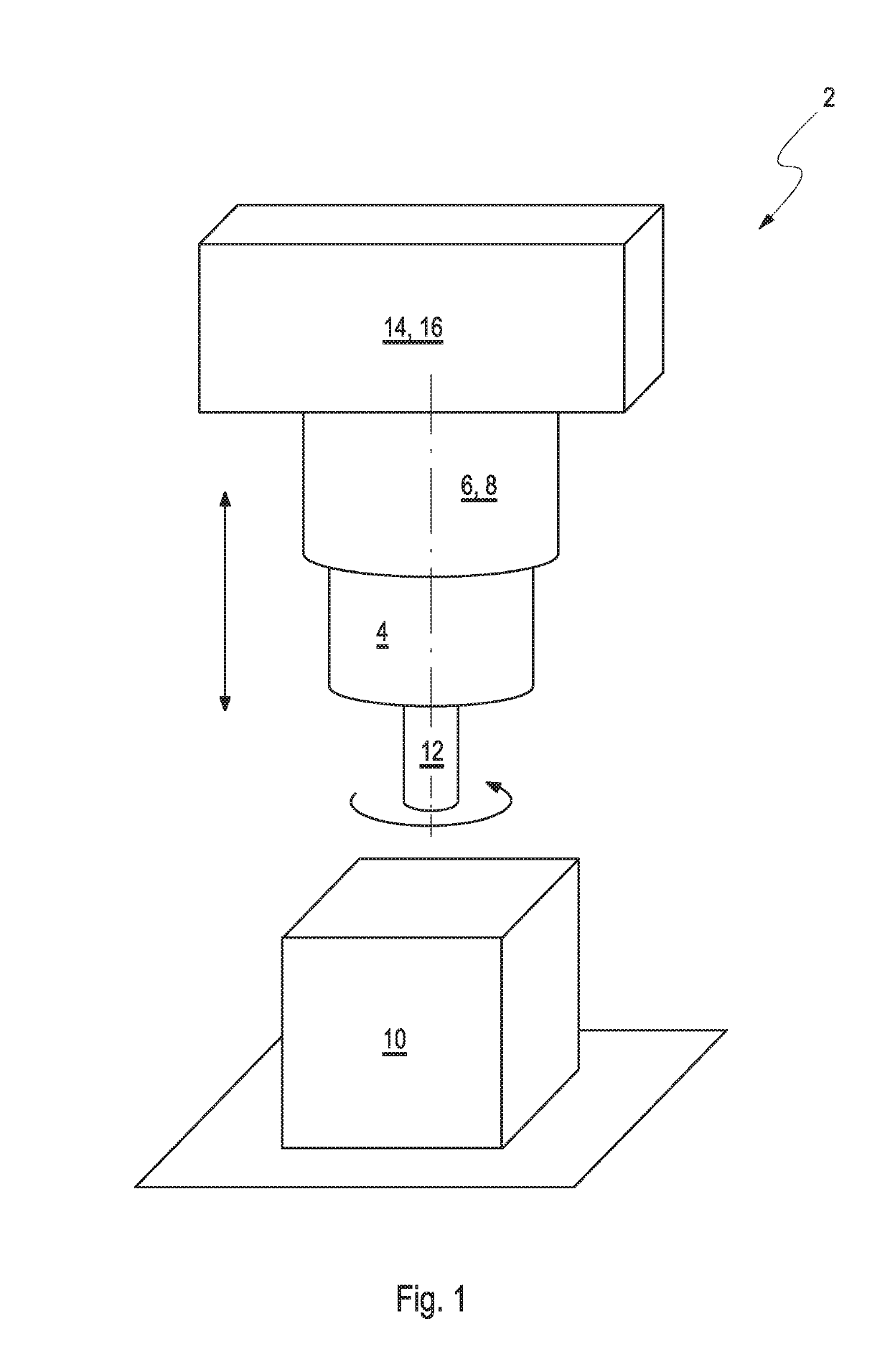
[0051]FIG. 1 shows a machine tool 2 provided overall with the reference numeral 2, which can be operated by a method according to FIG. 2. The machine tool 2 comprises a tool holder 4 and a tool holder 4 and a drivable, in particular electrical, rotary drive 6.

[0052]In addition, the machine tool 2 comprises a, in particular electrical, positioning drive 8, by which a distance between a workpiece 10 and the tool holder 4 is adjustable. In the tool holder 4, a tool 12 can be arranged, which is arranged rotationally fixed in the tool holder 4. In addition, the machine tool 2 shown in FIG. 1 comprises a control unit 16 comprising a storage means 14.

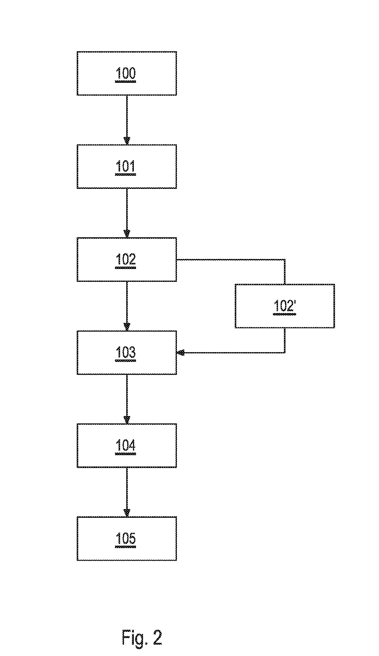
[0053]With reference to FIG. 2, with the aid of and reference to the individual components of the machine tool 2 shown schematically in FIG. 1, the method in accordance with the invention is described:

[0054]In a first method step 100, tool and / or workpiece data, such as dimensions and material, are detected or provided in the storage means 14 ...


PUM


Abstract

A method for detecting at least one tool state of a tool of a machine tool for machining workpieces, which includes at least one tool holder, at least one positioning drive, which includes at least one tool which is arrangeable or arranged rotationally fixed in the tool holder and which includes at least one control unit. The method includes the following steps: detecting or providing tool and / or workpiece data in the storage means and / or the control unit; providing at least one reference drive frequency of the rotary drive and / or the positioning drive; detecting at least one ACTUAL driving frequency of the rotary drive and / or the positioning drive; assigning the ACTUAL drive frequency of a reference drive frequency of the rotary drive and / or the positioning drive by the control unit and evaluating and / or interpreting at least the reference drive frequency associated with the ACTUAL drive frequency by the control unit.

Description

CROSS REFERENCE TO RELATED APPLICATIONS[0001]This application claims priority to Germany application DE 10 2017 128 628.4, filed Dec. 1, 2017, which is incorporated by reference in its entirety.[0002]The invention relates to a method for detecting at least one reference tool state of a tool of a machine tool for machining workpieces and a machine tool that can be operated by such a method.BACKGROUND[0003]Methods for detecting machining operations in and with machine tools are known. In this case, for example, detected and / or measured ACTUAL values of components of the machine tool are detected and compared with TARGET values in order to determine a proper operation of the machine tool or a deviation from a proper operation of the machine tool. Such a method is known, for example, from EP 13 163 801.[0004]In the known methods, it has proved to be disadvantageous that for detecting an ACTUAL state of a component of the machine tool, sensor means must be provided with which the respect...

Claims


Application Information

Patent Timeline
Patent Type & Authority Applications(United States)
IPC IPC(8): G05B19/4065
CPCG05B19/4065G05B2219/37252B23Q17/09B23Q17/0995B23Q17/0952B23Q17/10
Inventor BRAMBACH, TOBIASCAUET, CHRISTOPHEKRUSE, FLORIANHEINZ, JOCHEN
Owner POINT 8 GMBH
Why Eureka
Try Eureka