HVAC system including smart diagnostic capabilites

a technology of hvac system and smart diagnostic capability, applied in the field of hvac system, can solve the problems of inability to and only be determined, thermostats and/or bass do not include smart diagnostic capability, communication loss,

Active Publication Date: 2019-06-20
TRANE INT INC
View PDF17 Cites 8 Cited by
  • Summary
  • Abstract
  • Description
  • Claims
  • Application Information

AI Technical Summary

Benefits of technology

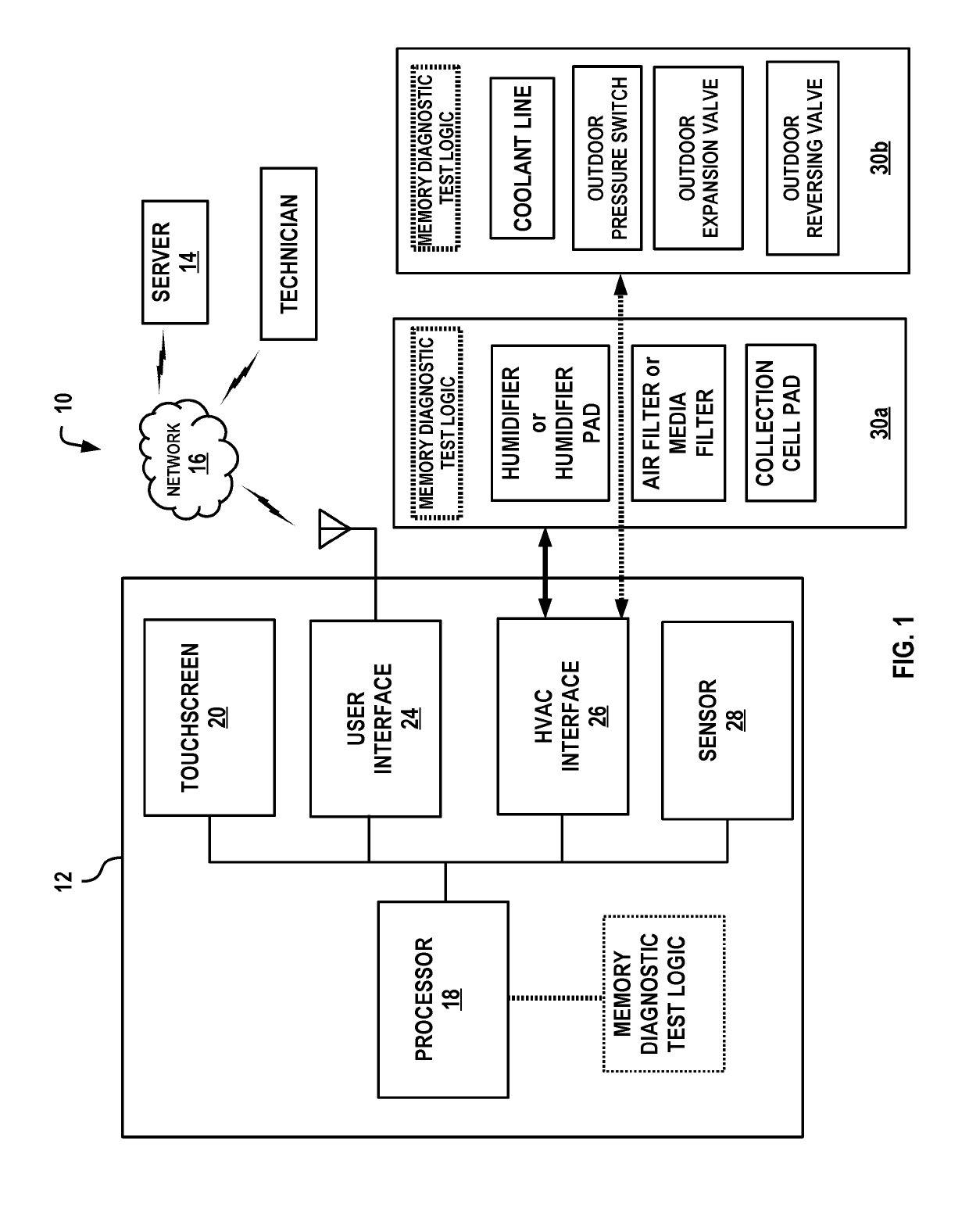
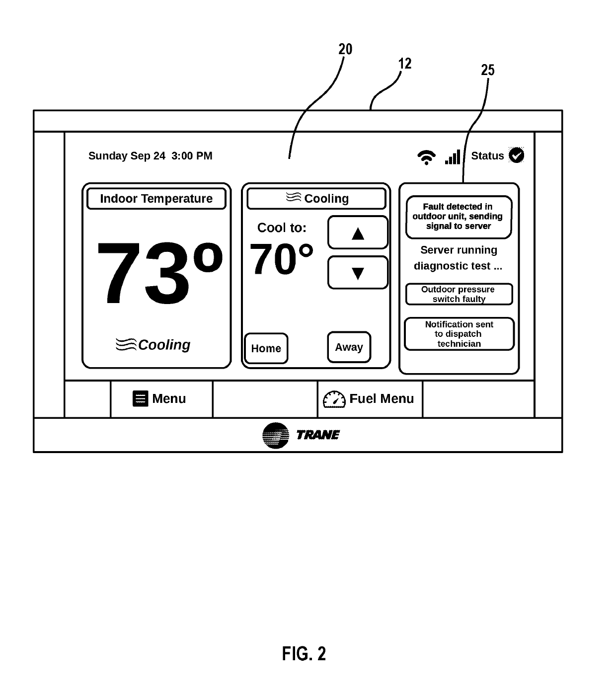
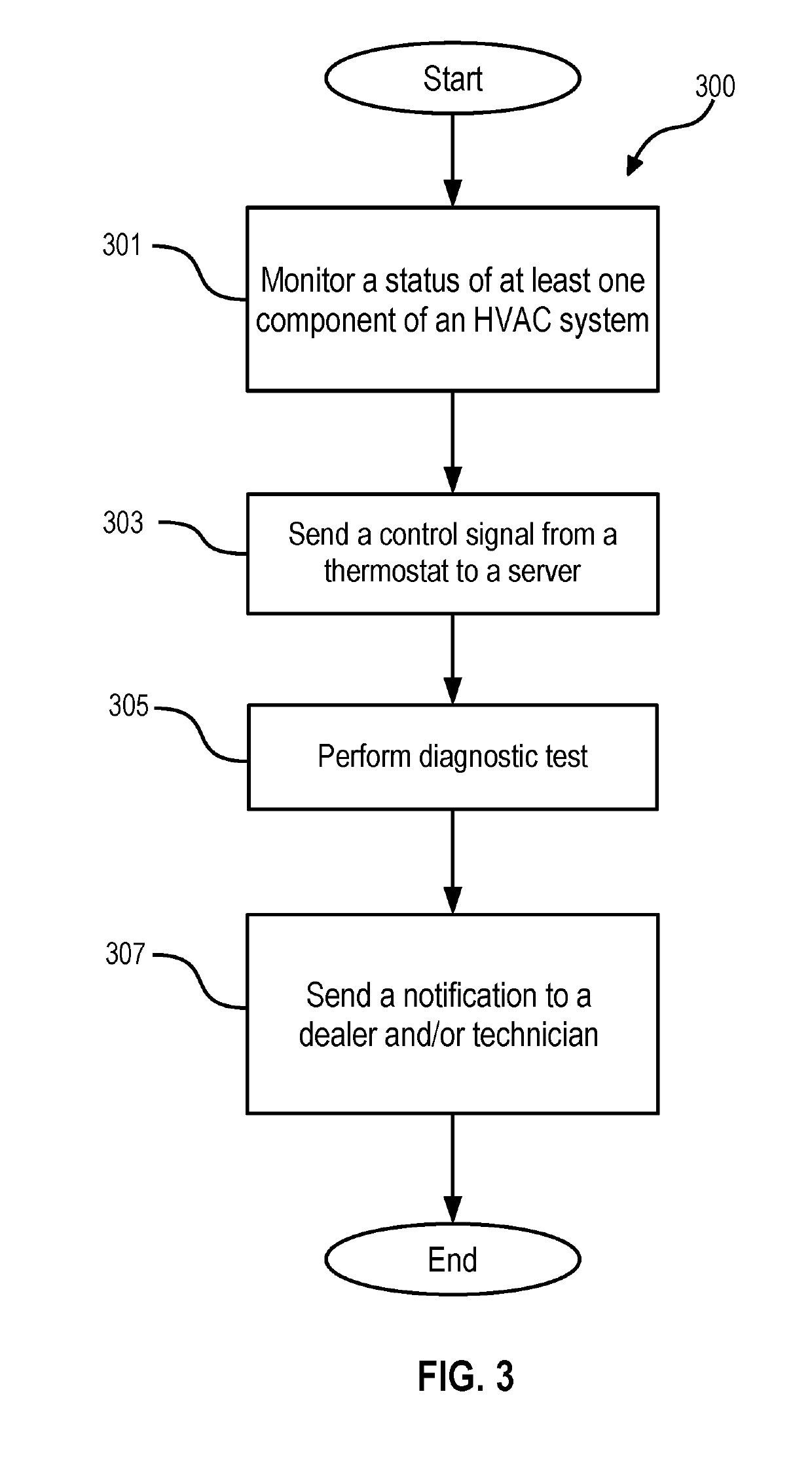
The present disclosure aims to provide an HVAC system with a thermostat that can communicate with a server to diagnose any faulty components in the system. This way, the technician can identify and fix the problem before reaching the location of the HVAC system. The technical effect of this is to improve the efficiency and efficiency of the HVAC system.

Problems solved by technology

These faults can be a result of faulty sensors, undesirable and extreme environmental conditions, communication loss (e.g., loss of connectivity between one or more of the HVAC peripherals, the thermostat or the BAS), etc.
While some of the faults can be predicted prior to occurring through continuous monitoring of the various operating parameters (e.g., temperature, pressure, etc.) of the HVAC system, most of them cannot and can only be determined after their occurrence.
While the aforementioned thermostats and / or BASs are suitable for providing a status of the peripheral components, such thermostats and / or BASs do not include smart diagnostic capabilities that would allow the thermostat and / or the BAS to perform a diagnostic test of the faulty HVAC peripherals, and subsequently notify a technician if their service is required.
The server can perform a system lockout of the HVAC system when it is determined that there is a likelihood that continued operation of the faulty at least one peripheral component can cause damage to at least one other peripheral component of the HVAC system.

Method used


Image

  • HVAC system including smart diagnostic capabilites
  • HVAC system including smart diagnostic capabilites
  • HVAC system including smart diagnostic capabilites

Examples


Embodiment Construction

[0029]Particular illustrative embodiments of the present disclosure are described hereinbelow with reference to the accompanying drawings; however, the disclosed embodiments are merely examples of the disclosure, which may be embodied in various forms. Well-known functions or constructions and repetitive matter are not described in detail to avoid obscuring the present disclosure in unnecessary or redundant detail. Therefore, specific structural and functional details disclosed herein are not to be interpreted as limiting, but merely as a basis for the claims and as a representative basis for teaching one skilled in the art to variously employ the present disclosure in any appropriately detailed structure. In this description, as well as in the drawings, like-referenced numbers represent elements which may perform the same, similar, or equivalent functions. The word “exemplary” is used herein to mean “serving as a non-limiting example, instance, or illustration.” Any embodiment desc...


PUM


Abstract

A system for remote diagnostic analysis of a heating, ventilation and air condition (HVAC) system is provided. The system includes a thermostat in operable communication with at least one peripheral component of the HVAC system and configured to receive information relating to the at least one peripheral component, and a server in operable communication with the thermostat for receiving and analyzing the information. The server causes the at least one peripheral component to conduct a diagnostic test and analyzes the test result to perform a root cause analysis of a system malfunction.

Description

BACKGROUNDField of the Disclosure[0001]The present disclosure generally relates to a heating, ventilation and air conditioning (HVAC) system, and more particularly, to an HVAC system including smart diagnostic capabilities.Description of the Related Art[0002]HVAC systems which regulate environmental conditions within an enclosed area of a commercial building (or residential home) are known. Residential HVAC systems are typically controlled by a thermostat, e.g., a smart thermostat. With respect to commercial buildings, the HVAC systems are typically controlled by a building automation system (BAS) or HVAC equipment control system. The thermostat or BAS can also be used to control security, lighting, power, etc. of the building.[0003]Conventional BASs and / or thermostats can be configured to monitor a status of connected HVAC peripherals (e.g., an indoor unit and / or an outdoor unit, or parts thereof) to determine if the HVAC peripherals are working properly (or if they are faulty).[00...

Claims


Application Information

Patent Timeline
IPC IPC(8): F24F11/30F24F11/32F24F11/38F24F11/49F24F11/64G05B15/02
CPCF24F11/30F24F11/32F24F11/38F24F11/49F24F11/64G05B15/02F24F2140/00F24F11/56F24F11/58F24F11/61F24F11/50G05B2219/24048G05B2219/2614G05B2219/2642G05B19/048
Inventor MASLEKAR, PRERANAMUTHUSWAMY, MAGESHKUMARGARRETT, CARL L
Owner TRANE INT INC
Why Eureka
Try Eureka