Polyaxial bone anchoring device and system including an instrument and a polyaxial bone anchoring device

a polyaxial bone and anchoring device technology, applied in the direction of internal osteosynthesis, internal osteosynthesis, osteosynthesis devices, etc., can solve the problems of increasing the locking force on the head, and achieve the effect of less force, less profile and more effective clamping for

Active Publication Date: 2019-06-27
BIEDERMANN TECH GMBH & CO KG
View PDF0 Cites 6 Cited by
  • Summary
  • Abstract
  • Description
  • Claims
  • Application Information

AI Technical Summary

Benefits of technology

[0009]The locking of the head is effected by rotating the locking ring in one direction around the central axis, and the unlocking is effected by rotating the locking ring in the opposite direction. With such a design, the size of a head receiving portion of the receiving part may be reduced in an axial direction to achieve a low profile. A further clinical advantage may be that the exertion of pressure onto the vertebrae when locking the head can be reduced as it is not necessary to move the locking ring downward for locking the head. Moreover, the unlocking requires less force compared to known devices in which the locking is achieved through engagement of two tapered surfaces of the locking ring and the head receiving portion, respectively.
[0010]The locking and unlocking of the bone anchoring device during surgery can also be carried out with the rod not yet inserted or being at an elevated position in the receiving part, away from the bottom of a rod receiving recess. This increases the possibilities of carrying out correction steps during surgery.
[0011]If additionally, a pressure member is provided for exerting pressure onto the head, the clamping force may be distributed onto the head more effectively. Moreover, when locking the rod, pressure exerted by the rod onto the pressure member may further increase the locking force onto the head.
[0012]The legs may each have a separable portion that forms extended tabs. The extended tabs allow convenient manipulation of the polyaxial bone anchoring device during surgery. Furthermore, the extended tabs permit guiding and/or supplying elements of an implant or instruments to the implantation site. This is particularly useful in the

Problems solved by technology

Moreover, when locking the rod, pressure exerted by the rod onto the pressure member may further increase the locking force onto the head.
Moreover, the

Method used


Image

  • Polyaxial bone anchoring device and system including an instrument and a polyaxial bone anchoring device
  • Polyaxial bone anchoring device and system including an instrument and a polyaxial bone anchoring device
  • Polyaxial bone anchoring device and system including an instrument and a polyaxial bone anchoring device

Examples


Embodiment Construction

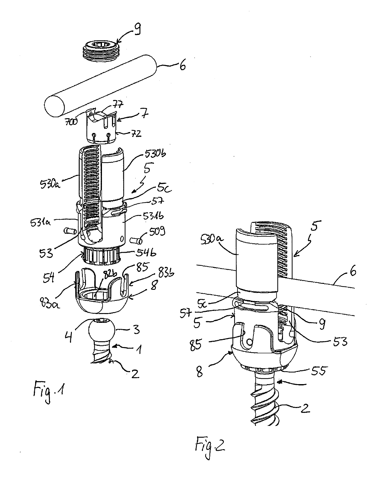
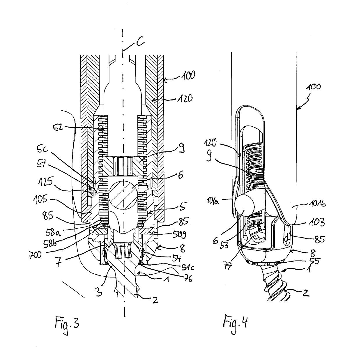
[0052]As shown in FIGS. 1 to 4, a polyaxial bone anchoring device according to an embodiment of the invention includes a bone anchoring element 1 in the form of, for example, a bone screw having a shank 2 with a threaded portion and a head 3 with a spherically-shaped outer surface portion. The head 3 may have a recess 4 for engagement with a driver. The bone anchoring device also includes a receiving part 5 for receiving a rod 6 to be connected to the bone anchoring element 1. In addition, a pressure member 7 may be provided in the receiving part 5 for exerting pressure onto the head 3 of the bone anchoring element 1. Further, the bone anchoring device includes a locking ring 8 that is mountable to the receiving part 5 for compressing a portion of the receiving part 5 to exert pressure onto the head 3. Lastly, the bone anchoring device also includes a fixation element 9, in the form of, for example, an inner screw or set screw for fixing the rod in the receiving part 5.

[0053]The rec...


PUM


Abstract

A bone anchoring device includes a receiving part having a central axis, two legs defining a recess for receiving a rod, and a head receiving portion that is at least partially expandable and having an opening for inserting and pivotably holding a head of a bone anchoring element therein, and a locking ring mountable around the head receiving portion in an axial direction while a rotational orientation of the locking ring relative to the receiving part remains constant. When the locking ring is around the head receiving portion, the locking ring is rotatable around the central axis from a first rotational orientation to a second rotational orientation where a compressive force exerted by the locking ring on the head receiving portion is greater than at the first rotational orientation.

Description

CROSS-REFERENCE TO RELATED APPLICATION(S)[0001]The present application claims priority to and the benefit of U.S. Provisional Patent Application No. 62 / 609,862, filed Dec. 22, 2017, the contents of which are hereby incorporated by reference in their entirety, and claims priority from European Patent Application EP 17 210 500.9, filed Dec. 22, 2017, the contents of which are hereby incorporated by reference in their entirety.BACKGROUND[0002]The invention relates to a polyaxial bone anchoring device and a system including a polyaxial bone anchoring device and an instrument for use with the device. More specifically, the bone anchoring device includes a receiving part for coupling a rod to a bone anchoring element and a locking ring for locking a head of the bone anchoring element and for releasing the locking, for example via the instrument.DESCRIPTION OF RELATED ART[0003]A polyaxial bone anchoring device of this type is known from US 2017 / 0020574 A1. The known polyaxial bone anchorin...

Claims


Application Information

Patent Timeline
IPC IPC(8): A61B17/70
CPCA61B17/7037A61B17/7032A61B17/7002A61B17/7076A61B17/7091A61B2017/7073A61B17/7035
Inventor BIEDERMANN, TIMODANNECKER, BERTHOLD
Owner BIEDERMANN TECH GMBH & CO KG
Why Eureka
Try Eureka