Route monitoring system and method

a monitoring system and route technology, applied in the direction of instruments, transportation and packaging, using reradiation, etc., can solve the problems of dispatch center not using the segment of the track used by the dispatch center, wayside monitoring system may not be able to identify, and disrupt the flow of traffic in the transportation network

Active Publication Date: 2019-06-27
GE GLOBAL SOURCING LLC
View PDF0 Cites 3 Cited by
  • Summary
  • Abstract
  • Description
  • Claims
  • Application Information

AI Technical Summary

Benefits of technology

[0008]The erroneous identification of a rail vehicle on the segment of track may only be identified by an operator after an extended period of time. Then, one or more persons may be required to travel to the route segment and visually inspect the segment of track to identify the cause of the errors by the wayside monitoring system. The wayside monitoring system may be unable to identify any potential cause for the errors to the persons seeking to repair the problem with the track.
[0009]In one embodiment, a monitoring method includes monitoring a transmitted current that is injected into conductive components of a route that is traveled by one or more vehicle systems, monitoring a received current that represents at least a portion of the transmitted current that is conducted through the conductive components of the route, examining changes in one or more of the transmitted current or the received current over time to determine when at least one of the vehicle systems is disposed on the route between a first location along the route where the transmitted current is injected into the conductive components and a different, second location along the route where the received current is monitored, and examining the same changes in the one or more of the transmitted current or the received current to identify at least one of a contaminated portion of a surface on which the conductive components of the route are disposed, to identify a foreign object other than the one or more vehicle systems that is contacting the conductive components of the route, or to identify a damaged or broken portion of at least one of the conductive components of the route.
[0010]In another embodiment, a monitoring system includes a transmit monitor and a receive monitor. The transmit monitor includes one or more processors configured to measure a transmitted current that is injected into conductive components of a route that is traveled by one or more vehicle systems. The receive monitor includes one or more processors (which may be one or more of the same processors as the transmit monitor or different processors than the transmit monitor) that are configured to measure a received current that represents at least a portion of the transmitted current that is conducted through the conductive components of the route. At least one of the transmit monitor or the receive monitor also is configured to examine changes in one or more of the transmitted current or the received current over time to determine when at least one of the vehicle systems is disposed on the route between a first location along the route where the transmitted current is injected into the conductive components and a different, second location along the route where the received current is monitored. At least one of the transmit monitor or the receive monitor is configured to examine the same changes in the one or more of the transmitted current or the received current to identify at least one of a contaminated portion of a surface on which the conductive components of the route are disposed, to identify a foreign object other than the one or more vehicle systems that is contacting the conductive components of the route, or to identify a damaged or broken portion of at least one of the conductive components of the route.

Problems solved by technology

For example, if another foreign object or body creates or forms a short or shunt in the circuit that includes the rails of the track, the wayside monitoring system that is monitoring that segment of the track may incorrectly determine that a rail vehicle is on the segment of the track.
This incorrect determination can result in disruption of the flow of traffic in a transportation network that includes the track.
Additionally or alternatively, the wayside monitoring system may incorrectly notify a dispatch center that the segment of the track is occupied, which can prevent the dispatch center from using that segment of the track to route rail vehicles.
The wayside monitoring system may be unable to identify any potential cause for the errors to the persons seeking to repair the problem with the track.

Method used


Image

  • Route monitoring system and method
  • Route monitoring system and method
  • Route monitoring system and method

Examples


Embodiment Construction

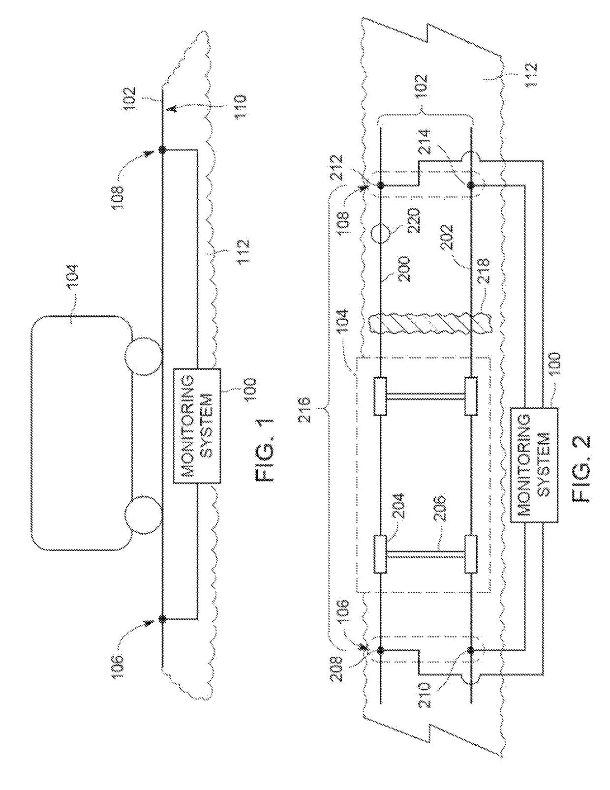
[0023]One or more embodiments of the inventive subject matter described herein provide monitoring systems and methods that monitor electrical characteristics of a segment of a route on which one or more vehicles may travel. The electrical characteristics are monitored in order to detect the presence of a vehicle system (e.g., a single vehicle, or two or more vehicles mechanically coupled together to travel together along the route, such as in a consist) on the route segment. For example, the route may include plural conductive components (e.g., rails) and the vehicle system may include wheels connected by axles that, when the wheels contact the conductive components of the route, form a conductive pathway or bridge between the conductive components of the route. The systems and methods described herein can monitor changes in electrical characteristics of the conductive components of the route (e.g., changes in an electric current transmitted and received along the conductive compone...


PUM

PropertyMeasurementUnit
speedaaaaaaaaaa
speedaaaaaaaaaa
distanceaaaaaaaaaa

Abstract

A monitoring method and system monitor a transmitted current that is injected into conductive components of a route traveled by vehicle systems, monitor a received current that represents a portion of the transmitted current that is conducted through the conductive components of the route, examine changes in the transmitted and/or received current over time to determine when the vehicle systems are on the route between a first location where the transmitted current is injected into the conductive components and a second location where the received current is monitored, and examine the changes in the transmitted and/or received currents. The changes are examined to identify (a) a contaminated portion of a surface on which the route is disposed, (b) a foreign object other than the vehicle systems that is contacting the route, and/or (c) a damaged or broken portion of at least one of the conductive components of the route.

Description

CROSS-REFERENCE TO RELATED APPLICATIONS[0001]This application is a continuation-in-part of U.S. patent application Ser. No. 15 / 345,158, which was filed on 7 Nov. 2016, and which is a continuation of U.S. patent application Ser. No. 14 / 512,729, which was filed on 13 Oct. 2014.[0002]U.S. patent application Ser. No. 14 / 512,729 claims priority to U.S. Provisional Application No. 61 / 912,069, which was filed on 5 Dec. 2013.[0003]The entire disclosures of all these applications are incorporated herein by reference.FIELD[0004]Embodiments of the inventive subject matter described herein relate to electrically monitoring a route traveled by one or more vehicle systems.BACKGROUND[0005]Some wayside monitoring systems monitor electric current that is conducted in rails of a track to determine when rail vehicles travel on certain segments of the track. When a rail vehicle travels on the segment of the track through which current is being conducted, the rail vehicle can short out a circuit that in...

Claims


Application Information

Patent Timeline
Patent Type & Authority Applications(United States)
IPC IPC(8): B61L23/04G01V3/02G01N27/20G01N27/04B61L15/00B61L1/18B61L1/20
CPCB61L23/041G01V3/02G01N27/20G01N27/041B61L15/0036B61L23/044B61L1/181B61L1/20B61L3/10B61L23/047B61L15/0081B61L1/02B61L23/00B61L23/04B61L23/042B61L23/045
Inventor WEINGARTNER, ARIC ALBERTMITTI, AARON RICHARD
Owner GE GLOBAL SOURCING LLC
Why Eureka
Try Eureka