Method of analyzing deformations in a laminated object and according system

a laminated object and deformation technology, applied in the field of non-destructive analysis of laminated objects, can solve the problems of negative affecting the quality of laminated objects, difficult process for manufacturing large composite structures, and fabrication flaws

Active Publication Date: 2017-11-14
VESTAS WIND SYST AS
View PDF12 Cites 0 Cited by
  • Summary
  • Abstract
  • Description
  • Claims
  • Application Information

AI Technical Summary

Benefits of technology

[0013]In further processing the topography in accordance with the above described embodiment, it is possible to more exactly localize defects as compared to using directly the topographical data itself for localizing defects, while defects may be more reliably identified and assessed with regard to their severity. In this way, false positives and false negatives as appearing in the topographical data are identifiable as such.
[0026]In a further illustrative embodiment, the memory device may comprise data indicating a severity of various kinds of surface defects associated to respective values of applied load. The person skilled in the art will appreciate that a severity of defects may be reliably identified and erroneous identification of false positives may be easily avoided.

Problems solved by technology

In general, defects in material of a laminated object induce strain anomalies resulting in structural weaknesses which may negatively affect the quality of a laminated object.
In particular tolerances and / or problems appearing in one or more process steps of a manufacturing processes for manufacturing laminated objects represent sources of material defects, and therefore strain anomalies, and compliance with quality standards requires examination of manufactured products in this respect to approve load capacitance with regard to future applications.
The manufacturing of these large composite structures is a difficult process that is normally performed with skilled manual labor.
Particularly during the manufacturing of blades for wind turbine power installations, fabrication flaws such as delamination between layers of composite material, wrinkles or waviness between layers of composite material, lack of bond or debonds between bond lines of structural elements and leading and trailing edges of blades and wrinkled or bent fibers of fibered blade materials may appear, for instance, due to complexities in the blade manufacturing process.
With their large sizes, wind turbine blades are very difficult to inspect while, on the other hand, the possible flaws or damages are very small in size in comparison with the whole blade.
As many fabrication flaws are not even visible to the surface, visual examination of the surface may not be considered as providing an effective testing method for detecting fabrication flaws and assessing the quality of manufactured blades.
However, known shearography methods do not allow to unambiguously detect all relevant defects because, on the one hand, washed out defects may not appear in measurements, these defects representing “false negatives”.
On the other hand, artifactual signals may indicate the presence of defects where no defect exists, these signals representing “false positives”.

Method used


Image

  • Method of analyzing deformations in a laminated object and according system
  • Method of analyzing deformations in a laminated object and according system
  • Method of analyzing deformations in a laminated object and according system

Examples


Embodiment Construction

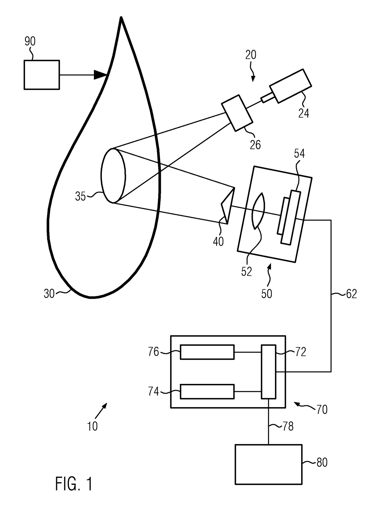
[0038]The present invention relates to a method of analyzing a laminated object and to a system for analyzing a laminated object. The preferred embodiments, as subsequently described, illustrate optical interferometry techniques for non-destructively analyzing laminated objects with large surfaces. Herein, various optical interferometry techniques are utilized to obtain data relating to the topography of an object under examination and, thereof, to determine topographical data of the object. The topographical data is further processed so as to identify type, severity and / or position of defects.

[0039]In accordance with an illustrative example, a shearography method may be performed for analyzing a laminated object. Herein, at least a surface portion of the laminated object is exposed to a coherent electromagnetic radiation which is in turn detected by means of an imaging device. Generally, a shearing element is disposed in the light path, either upstream or downstream the laminated o...


PUM


Abstract

The present invention relates to a method of analyzing a laminated object and to a system for analyzing a laminated object. Illustrative embodiments herein relate to optical interferometry techniques for non-destructively analyzing laminated objects with large surface utilized to obtain data relating to the topography of an object under examination and to further process the obtained topographical data so as to identify type and / or severity and / or position of surface defects.

Description

BACKGROUND OF THE INVENTION[0001]1. Field of the Invention[0002]The present invention generally relates to a method of analyzing a laminated object and a system for analyzing a laminated object. Particularly, the present invention relates to non-destructively analyzing laminated objects such as composite blades for wind turbine installations.[0003]2. Description of the Related Art[0004]In general, defects in material of a laminated object induce strain anomalies resulting in structural weaknesses which may negatively affect the quality of a laminated object. In particular tolerances and / or problems appearing in one or more process steps of a manufacturing processes for manufacturing laminated objects represent sources of material defects, and therefore strain anomalies, and compliance with quality standards requires examination of manufactured products in this respect to approve load capacitance with regard to future applications.[0005]Depending on the type and size of manufactured ...

Claims


Application Information

Patent Timeline
Patent Type & Authority Patents(United States)
IPC IPC(8): G01B11/02G06T11/20F03D17/00G01B11/16
CPCG01B11/162G06T11/206F03D17/00
Inventor ENEVOLDSEN, GEORG HERBORGSCHRODER, HENNINGHALLING, KAJ MORBECH
Owner VESTAS WIND SYST AS
Why Eureka
Try Eureka