Determining the Robot Axis Angle and Selection of a Robot with the Aid of a Camera

a technology of robot axis and camera, which is applied in the direction of programme-controlled manipulators, image data processing, programme control, etc., can solve the problems of inability to read, method is relatively involved, and markings might be temporarily obscured

Active Publication Date: 2016-12-01
KUKA ROBOTER
View PDF0 Cites 2 Cited by
  • Summary
  • Abstract
  • Description
  • Claims
  • Application Information

AI Technical Summary

Benefits of technology

[0021]The portable terminal device preferably comprises a display part, which depicts the detected image. Therefore, a user of the portable terminal device can immediately recognize whether a matching image of the manipulator to be identified was detected or not. As a result, an erroneous identification by detecting an image a manipulator that is not to be identified can be prevented.

Problems solved by technology

This is disadvantageous, however, because the address must be known and entered.
As a result, the method is relatively involved.
However, this method is also associated with disadvantages, because said markings or tags must be attached to the relevant control system or mechanics.
Furthermore, it is also possible that these markings might be temporarily obscured due to an unfavorable configuration, and therefore cannot be read.
Consequently, the method is likewise relatively involved and, moreover, unreliable.

Method used


Image

  • Determining the Robot Axis Angle and Selection of a Robot with the Aid of a Camera
  • Determining the Robot Axis Angle and Selection of a Robot with the Aid of a Camera
  • Determining the Robot Axis Angle and Selection of a Robot with the Aid of a Camera

Examples


Embodiment Construction

[0024]The present invention will be described in greater detail in the following making reference to the enclosed drawings, which show:

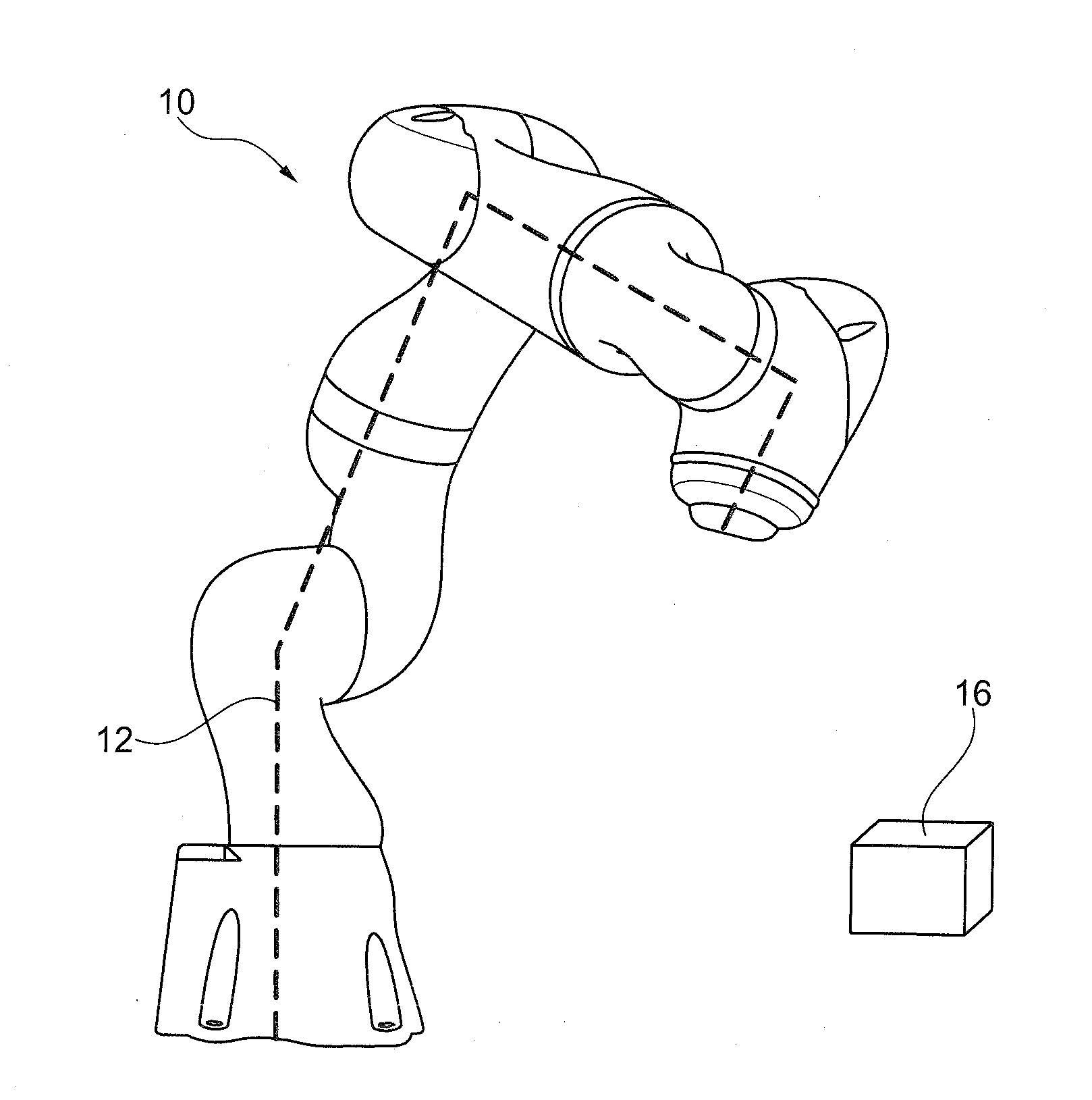
[0025]FIG. 1 An example of a manipulator to be identified;

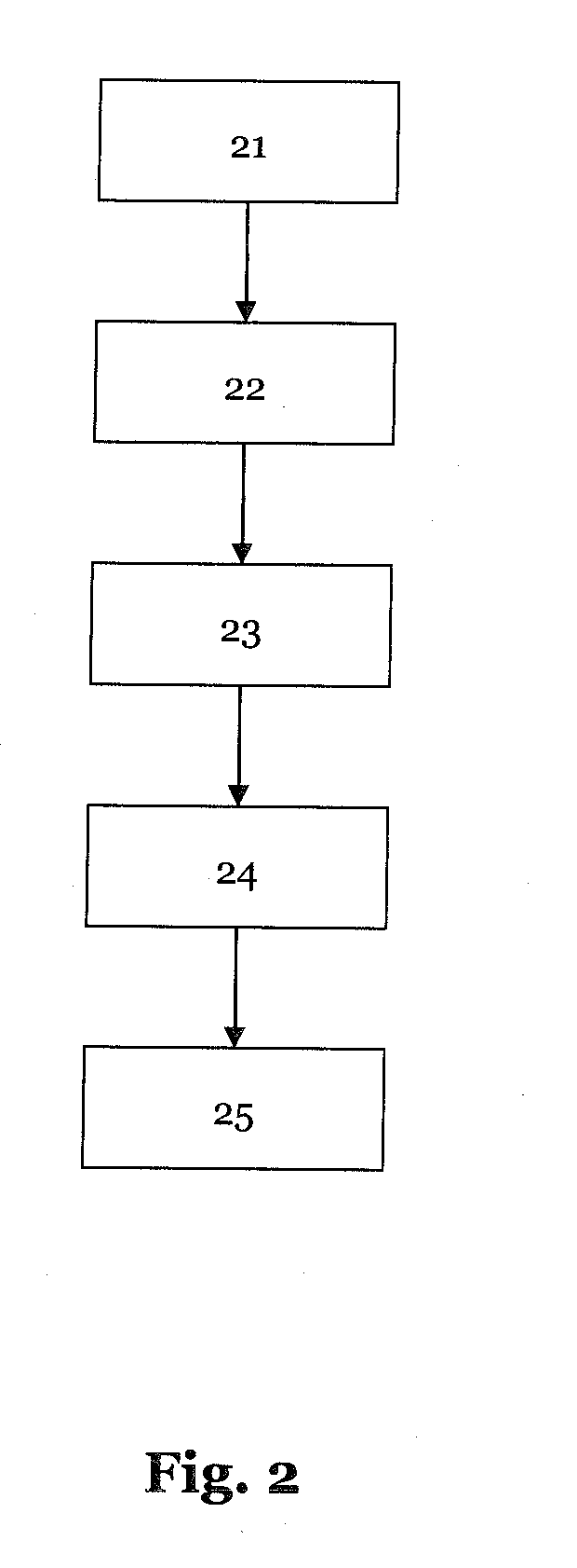
[0026]FIG. 2 The sequence of a method according to the invention for identifying a manipulator, and

[0027]FIG. 3 The sequence of another method according to the invention for identifying a manipulator.

[0028]FIG. 1 shows an example of a manipulator 10, which is configured as a multi-axle jointed-arm robot. The depicted manipulator 10 is located, for example, in a factory hall together with other manipulators (not shown), and is supposed to be identified and addressed from the plurality of said manipulators by means of a portable terminal device 16.

[0029]The portable terminal device 16 thereby comprises a 3D camera (not shown), which is a plenoptic camera and is based on the principle of light field sensors. To identify the manipulator 10, a three-dimensional image is recorded with the portable t...


PUM


Abstract

A method for identifying a manipulator by means of a portable terminal device, wherein the portable terminal device comprises a 3D camera. The method operates to detect a three-dimensional image of at least one part of the manipulator to be identified by means of the 3D camera of the portable terminal device. An actual status of the manipulator is determined based on the three-dimensional image detected. The 3D camera is a plenoptic camera, and the detected three-dimensional image comprises a four-dimensional light field of at least one part of the manipulator to be identified.

Description

[0001]This application claims the benefit of priority under 35 §119(a) to German Patent Application No. 10 2015 209 896.6, filed on May 29, 2015.1. TECHNICAL FIELD[0002]The present invention relates to a method for identifying a manipulator by means of a portable terminal device, as well as a corresponding portable terminal device and a robotic system.2. TECHNICAL BACKGROUND[0003]Manipulators, and especially industrial robots, are automatically controlled, freely programmable, multi-purpose machines. They can be used for example in different areas of a manufacturing facility in order to process or measure a component or workpiece, for example, in a processing station or a measuring station. Several manipulators are normally deployed in spatial proximity to one another in an industrial environment, and they are able to carry out different, similar or the same tasks.[0004]In modern industrial facilities with a certain degree of automation technology there is often a need to retrieve s...

Claims


Application Information

Patent Timeline
Patent Type & Authority Applications(United States)
IPC IPC(8): B25J9/16G06T7/00G06K9/00H04N13/02
CPCB25J9/1679H04N13/0203G06T7/0022G06K2209/19G06T7/0004G06T2207/10012G06K9/00201G06V20/64G06V20/10B25J9/1656G05B2219/39448G05B2219/39453G06T7/97H04N13/204B25J9/106B25J9/1697B25J19/023G02B3/0006G03B35/08G06V2201/06
Inventor HIETMANN, GERHARD
Owner KUKA ROBOTER
Why Eureka
Try Eureka