Method and Arrangement for Monitoring the Voltage on Electrical Storage Units, Battery and Motor Vehicle having such a Battery

a technology for electrical storage units and motor vehicles, applied in resistance/reactance/impedence, instruments, transportation and packaging, etc., can solve problems such as undervoltage being identified erroneously, overvoltage not being identified, and battery fire or leakage of dangerous chemical substances, so as to improve cell capacitance utilization

Active Publication Date: 2013-12-05
ROBERT BOSCH GMBH +1
View PDF4 Cites 1 Cited by
  • Summary
  • Abstract
  • Description
  • Claims
  • Application Information

AI Technical Summary

Benefits of technology

[0013]One particular advantage of the disclosure is that cell capacitances can be utilized better. This is achieved by virtue of the method according to the disclosure for monitoring the voltage on at least one electrical storage unit involving the idle voltage U_OCV on the at least one electrical storage unit being extracted from a voltage U_measured that is measured on the at least one electrical storage unit. By way of example, the at least one electrical storage unit may be a battery, preferably a traction battery in an electric or hybrid vehicle. In one preferred embodiment, the electrical storage unit comprises at least one electrochemical cell, but preferably a multiplicity of electrochemical cells. In this case, a plurality of, that is to say at least two, electrochemical cells may in turn be combined to form an electrochemical module. Since the measured voltage U_measured comprises not only the idle voltage U_OCV but also a further voltage portion, namely a current-dependent voltage portion U_ohm, which is not relevant to the safety of the at least one electrical storage unit or to the cell loading, the monitoring of the voltage can be specified in that the idle voltage U_OCV is extracted, in particular calculated, from the measured voltage U_measured. In one preferred embodiment, the idle voltage U_OCV is extracted by eliminating a current-dependent portion U_ohm of the measured voltage U_measured.

Problems solved by technology

The chemistry of these batteries means that they have a hazard potential—if operating limits are exceeded, there may be a battery fire or leakage of dangerous chemical substances.
Therefore, the nonreactive influences can result in 1) an overvoltage not being identified or 2) an undervoltage being identified erroneously.
In this case, this hardware monitoring is usually limited to just one input parameter—the voltage itself—on account of the circuit complexity.
These effects cannot be quantified by the conventional monitoring.

Method used


Image

  • Method and Arrangement for Monitoring the Voltage on Electrical Storage Units, Battery and Motor Vehicle having such a Battery
  • Method and Arrangement for Monitoring the Voltage on Electrical Storage Units, Battery and Motor Vehicle having such a Battery

Examples


Embodiment Construction

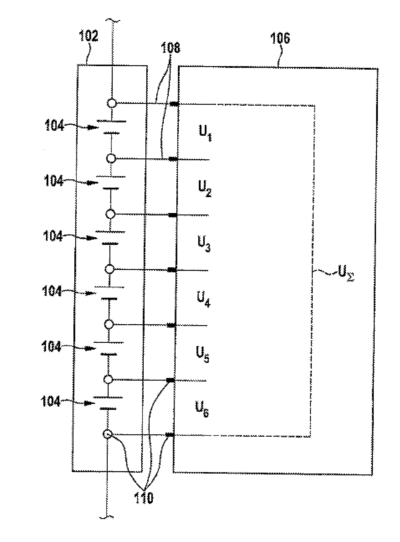
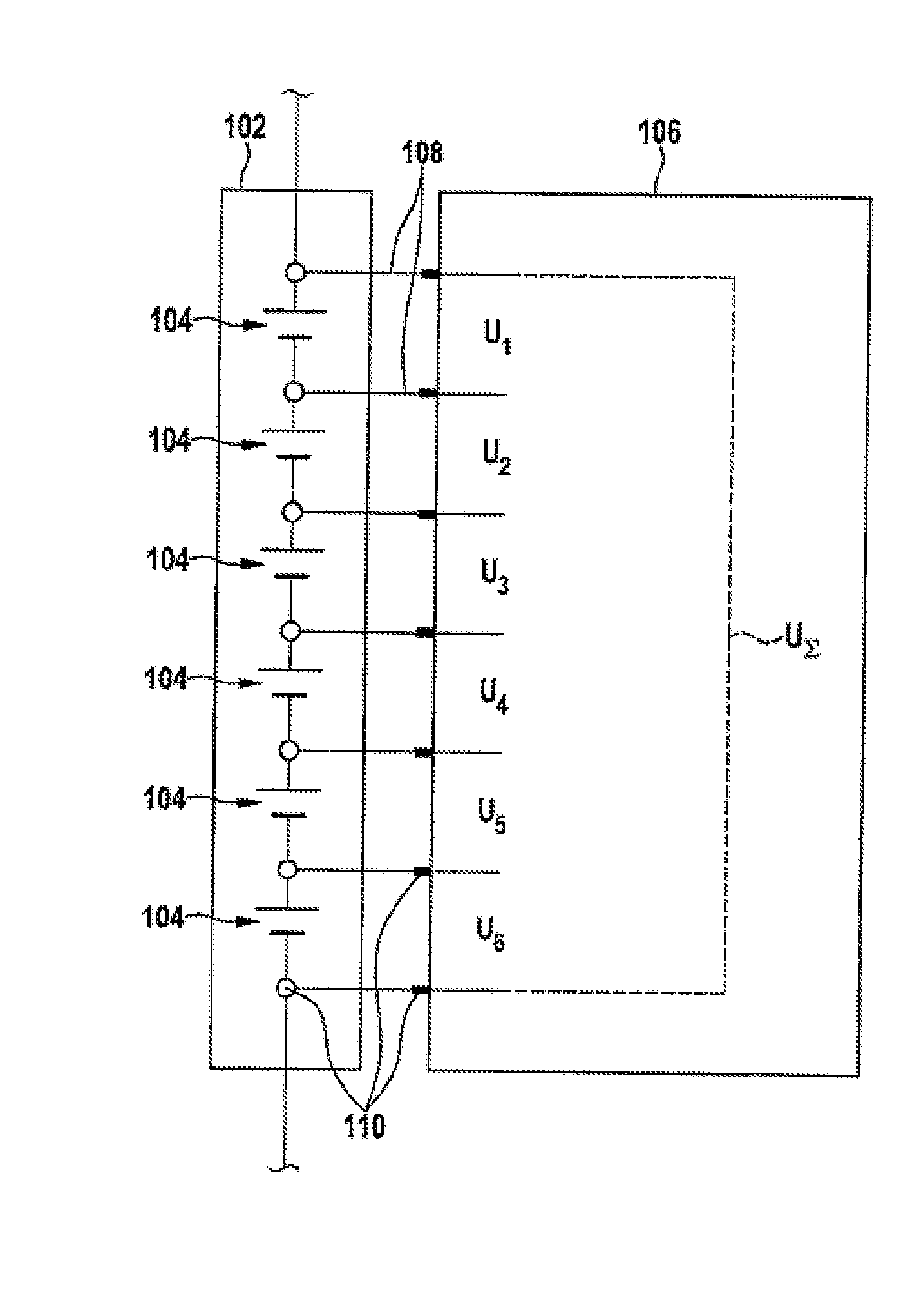
[0029]The FIGURE shows an exemplary battery module 102 having six battery cells 104 and a measuring unit 106. The cells 104, the measuring lines 108 and the contact points 110 contribute to the total nonreactive resistance of the system.

[0030]The measuring unit 106 measures the voltage Ui (i=1,2, . . . ,6) of every single battery cell 104 and determines the module voltage UΣ therefrom. The measured voltages Ui (i=1,2, . . . ,6) of the battery cells 104 each contain the idle voltage Ui_OCV and the current-dependent portion Ui_ohm (I, R), which is dependent on the current I and the nonreactive resistance R of the battery cell 104_i, the contact points 110 and the measuring lines 108 between the battery cell 104_i and the measuring unit 106 (i=1,2, . . . ,6).

[0031]On the basis of the formula

Ui—OCV=UI+Ui_ohm (I,R),

Ui_OCV can be calculated for any battery cell 104 directly or from a family of characteristic curves. It is found to be advantageous if further parameters, such as the tempera...


PUM


Abstract

The present disclosure relates to a method for monitoring the voltage on electrical storage units, to a battery and to a motor vehicle having such a battery that are configured to be used particularly for improved establishment of overvoltages and/or undervoltages on modules of the electrical storage unit. To this end, a method for monitoring the voltage on at least one electrical storage unit includes extracting an idle voltage U_OCV on the at least one electrical storage unit from a voltage U_measured that is measured on the at least one electrical storage unit.

Description

[0001]This application claims priority under 35 U.S.C.§119 to patent application no. DE 10 2012 209 308.7, filed on Jun. 1, 2012 in Germany, the disclosure of which is incorporated herein by reference in its entirety.BACKGROUND[0002]The present disclosure relates to a method and an arrangement for monitoring the voltage on electrical storage units, to a battery and to a motor vehicle having such a battery that are able to be used particularly for improved establishment of overvoltages and / or undervoltages on modules of the electrical storage unit.[0003]For the supply of power to electric drives in electric and hybrid vehicles, high-voltage lithium ion batteries are frequently used. The chemistry of these batteries means that they have a hazard potential—if operating limits are exceeded, there may be a battery fire or leakage of dangerous chemical substances.[0004]It is a task of the battery management system (BMS) to regulate the charging and discharge of the battery under the given...

Claims


Application Information

Patent Timeline
Patent Type & Authority Applications(United States)
IPC IPC(8): G01R31/36
CPCG01R31/3606G01R31/3648G01R31/3835G01R31/396Y02T10/70G01R31/382
Inventor FEUCHTER, WILFRIEDHEYL, ANDREASWEBER, JOCHENKRIEG, BERENGARBISHT, SANDEEP
Owner ROBERT BOSCH GMBH
Why Eureka
Try Eureka