Detector for sunken condition of vehicle

a technology for detecting the condition of vehicles and sunken vehicles, which is applied in the direction of vehicle components, anti-theft devices, tyre measurements, etc., can solve the problems of inability to function, technology disclosed, and japanese patent publication tokkai 11 to achieve the effect of quickly and reliably detecting the condition

Inactive Publication Date: 2008-05-20
ORMON CORP
View PDF12 Cites 4 Cited by
  • Summary
  • Abstract
  • Description
  • Claims
  • Application Information

AI Technical Summary

Benefits of technology

[0010]It is therefore an object of this invention to provide a detector for a sunken condition of a vehicle capable of detecting the sunken condition quickly and reliably without requiring a sensor for detecting a sunken condition.
[0012]In the above, the specified rate of change may be a preliminarily set range or a range that may be appropriately adjusted according to various parameters such as the absolute value of the tire air pressure and the running speed of the vehicle. A change being momentarily observed means that a change in the tire air pressure at a specified rate is observed for a specified number of times or over a specified length of time. The air tire pressure may mean the air pressure in one of the plurality of tires or the pressure in all of the tires. In other words, the controller may be set to identify a sunken condition when a certain rate of change in the air pressure is observed for one of the tires or when it is observed regarding all of the tires. In the case of a four-wheeled vehicle, the identification of a sunken condition may be based on observation on any two of the wheels such as mutually adjacent wheels (both front wheels, both rear wheel, both wheels on the left-hand side or both wheels on the right-hand side) or two wheels that are mutually diagonally located. Such modes of identification are advantageous because an erroneous identification of a sunken condition can be avoided when the air pressure in only one of the wheels drops when the vehicle is jacked up, say, for inspection. Identifications by two mutually adjacent wheels are advantageous also because a sunken condition can be identified, say, even when only one side of the vehicle has sunk in water.

Problems solved by technology

Since this device does not have the function of detecting whether the vehicle is in a sunken condition or not, it cannot function so as to enable only operations in a specified direction (such as the direction of opening the window) while disabling other operations at the time of a sunken condition or to leave a record of the sunken condition.
The technology disclosed in aforementioned Japanese Patent Publication Tokkai 11-36700 is not satisfactory because detection does not take place until the invasion of water into the vehicle makes a certain level of progress after the vehicle falls into water (such as a river, the sea, or flood water) such that the water level reaches the control box.
This means that a sunken condition is not always detected sufficiently quickly.
Although it may be hoped that power windows can function normally unless the control box is completely immersed in water, there is a high possibility that there may be a leakage elsewhere such that the actuators for the power windows cannot function normally while the control box is still capable of functioning correctly.
To set a sensor apart from the control box, however, complicates the construction and tends to increase the weight of the vehicle.
There is also the disadvantage that an extra space for the setting is required and there is the problem of reaching a mistaken conclusion if water is splashed thereupon while the vehicle is running in rain.
Since a sunken condition is not detected unless the tire is found to be in a non-contacting condition with the road surface, the sunken condition may not be detected sufficiently quickly.
Since a sensor must be set apart from the control box, furthermore, there is the same disadvantage as with the aforementioned technology according to Japanese Patent Publications Tokkai 2000-204843, 10-292731 and 11-22301.

Method used


Image

  • Detector for sunken condition of vehicle
  • Detector for sunken condition of vehicle
  • Detector for sunken condition of vehicle

Examples


first embodiment

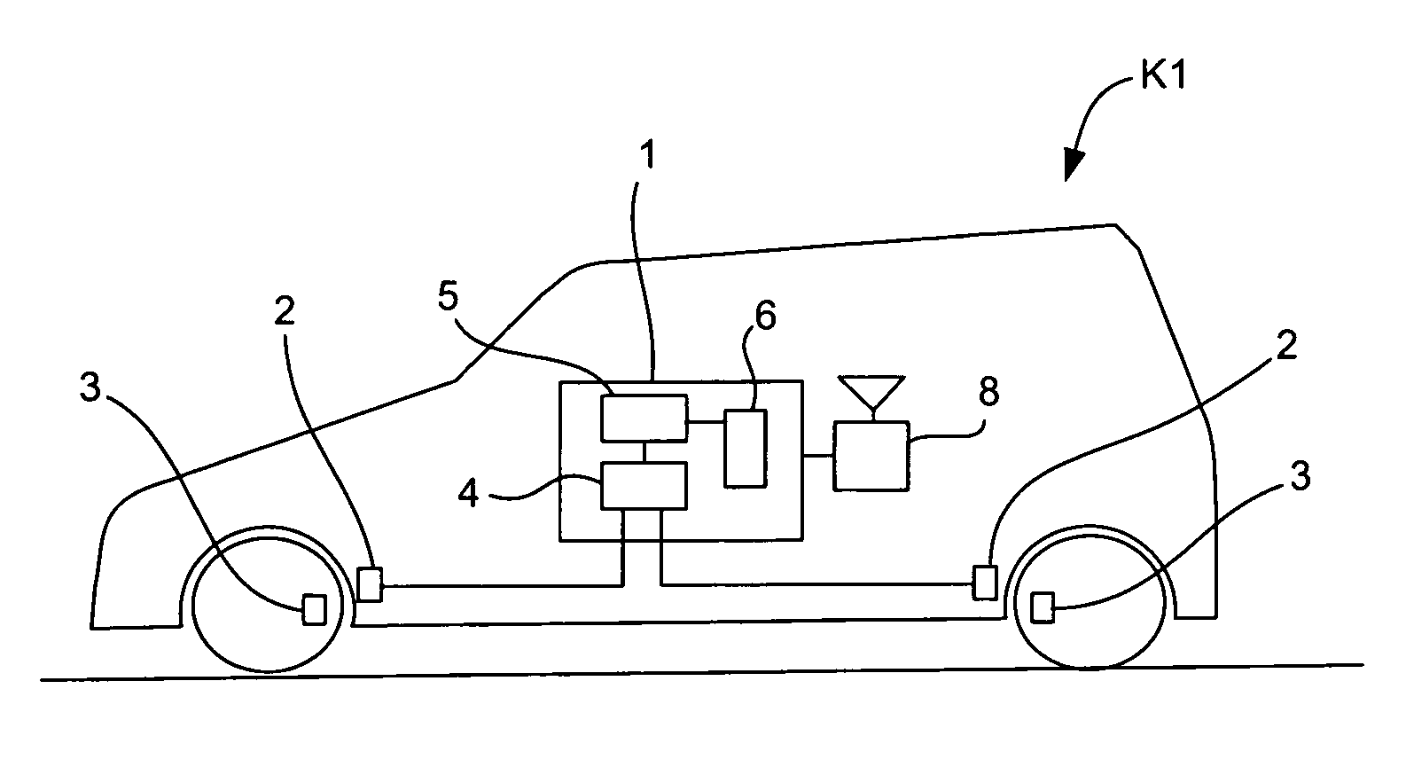
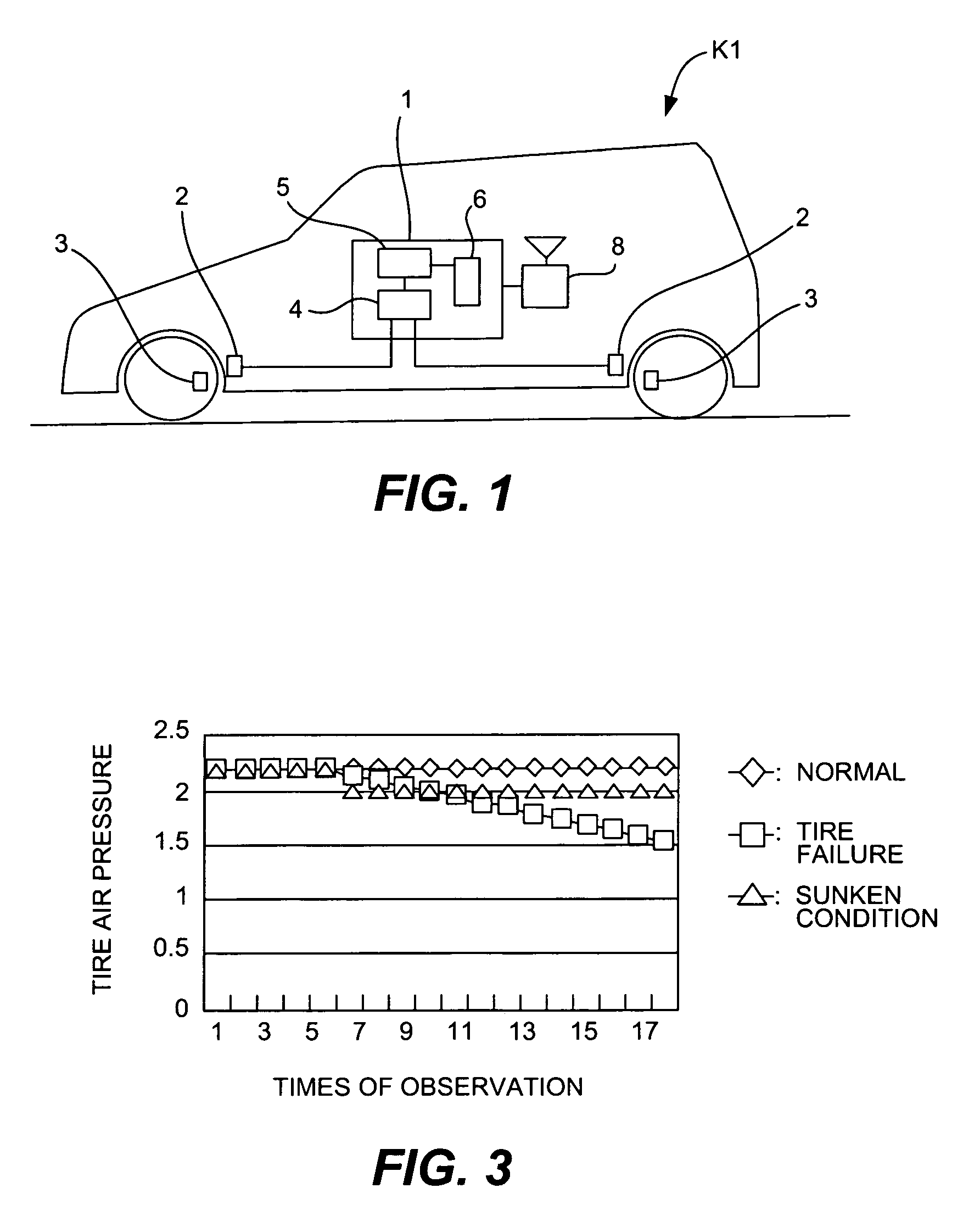
[0028]FIG. 1 shows a four-wheel vehicle K1 provided with a tire pressure monitoring system (TPMS) and a detector according to this invention. The elements that comprise the TPMS include a controller 1, antennas 2 and sensor units 3. The controller 1 is that of the TPMS set inside a control box carried by the vehicle and is provided with a microcomputer and a communication circuit (at least for reception), serving to receive through the antennas 2 wireless signals transmitted periodically from the sensor units 3, to read air pressure data contained in the wireless signals and to output an alarm (by sound, light and / or a character display) to inform the user if, for example, the air pressure value of a tire has dropped below an allowable level. The antennas 2 are each set near a corresponding one of the tires such as inside the tire housing and serve to receive wireless signals from the corresponding one of the sensor units 3, and to input them to the controller 1.

[0029]The sensor uni...

second embodiment

[0044]A detector of a sunken condition may be described also by FIG. 1 except that the controller 1 and the sensor units 3 are adapted to carry out two-way telecommunications. In other words, the controller 1 according to this embodiment of the invention is adapted to carry out not only the basic controls as a TPMS but also processes according to the flowchart shown in FIG. 4 to identify a sunken condition of the vehicle.

[0045]To explain more in detail, the controller 1 according to this embodiment of the invention carries out, for example, the processes of the flowchart of FIG. 4 periodically, by initially setting the value of a communication error counter to zero (Step S11) and next checking whether or not the processes of Steps S15-S18 have been completed (Step S12). If the judgment in Step S12 is YES, the controller 1 proceeds to Step S19. If the judgment in Step S12 is NO, the controller proceeds to Step S15.

[0046]In Step S15, the controller sends a request signal to the senso...

third embodiment

[0050]the present invention relates to a detector for a vehicle equipped with an electric power steering system (EPS). As shown in FIG. 5, the EPS includes a steering wheel 11 with a steering shaft 11a, a pinion gear 12 connected to the steering wheel 11 through the steering shaft 11a and a rack shaft 13 corresponding to the pinion gear 12, numerals 14 each indicating a tire. The EPS further includes a torque sensor 15 for detecting the steering torque exerted on the steering wheel 11, a motor 16 for generating a steering force, a driving mechanism 17 for transmitting the steering force to the rack shaft 13 and a controller 18 for controlling the current to the motor 16 (or output of the motor 16) according to the detected steering torque. Speed signals indicative of the traveling speed of the vehicle outputted from a speed sensor 19 and power from a battery 20 are also supplied to the controller 18.

[0051]The controller 18 functions not only to carry out the basic processes of an EP...


PUM


Abstract

A sunken condition of a vehicle provided with a sensor for measuring air pressure inside a tire, a communication device that carries out wireless communications between a vehicle main body and a tire, a steering torque sensor that measures steering torque, a sensor for measuring rotary speeds of driver and follower wheels of the vehicle or a navigating apparatus including a global positioning system and a dead-reckoning device is detected by a detector having a controller without requiring a sensor for detecting the sunken condition. The controller identifies a sunken condition on the basis of a momentary change in detected data, the status of communication from the sensor, a drop in the measured steering torque, a relative drop of the rotary speed of a follower wheel with respect to that of a driver wheel or a disagreement in measured position data by the navigating apparatus.

Description

[0001]Priority is claimed on Japanese Patent Application 2003-381369 filed Nov. 11, 2003.BACKGROUND OF THE INVENTION[0002]This invention is in the technical field of detecting the sunken condition of a vehicle in order to improve the safety of the power window function of a vehicle (such as an automobile) and in particular the function of opening the window such that the occupant can escape from a vehicle sunk in water.[0003]Recently, power window systems are coming to be provided with a control circuit for detecting the sunken condition of a vehicle in order to facilitate the escape of occupants dependably from such a vehicle under such a condition. Japanese Patent Publication Tokkai 11-36700, for example, disclosed a technology of preventing a vehicular window from acting on its own will at the time of sinking in water by providing a detection sensor for a sunken condition inside the control box of a power window system such that the relays for driving motors for the windows in bo...

Claims


Application Information

Patent Timeline
Patent Type & Authority Patents(United States)
IPC IPC(8): B60C23/00B60C23/02B60C23/04B60C23/06
CPCB60C23/0408
Inventor FUJIOKA, RYOJI
Owner ORMON CORP
Why Eureka
Try Eureka