Adaptive railway fastener and anchor installation system

a technology of rail fastener and installation system, which is applied in the field of railways, can solve the problems of inefficiency, personal injury risk, and maintenance of way, and achieve the effect of facilitating alignmen

Active Publication Date: 2019-06-27
MOW EQUIP SOLUTIONS INC
View PDF0 Cites 7 Cited by
  • Summary
  • Abstract
  • Description
  • Claims
  • Application Information

AI Technical Summary

Benefits of technology

[0009]Various embodiments of the system may further include a self-centering assembly that includes the pair of anchor tools and that is slidably coupled with a dual-beam support framework. Various embodiments of the system may further include a floating cylinder coupled with the pair of anchor tools and operable to cause sliding movement of the pair of anchor tools with respect to the dual-beam support framework. In various embodiments, the linkage system may include one or more cylinders attached to a main shaft structure and attached to the self-centering assembly so that the self-centering assembly is disposed below the main shaft structure. In various embodiments, the main shaft structure may be slidably coupled with a main shaft, and the railway component handling system may further include a main shaft cylinder attached to the main shaft structure and operable to selectively slide the main shaft structure along the main shaft.
[0010]Various embodiments of the system may further include a system controller configured to facilitate alignment of the railway anchor manipulator and the railway fastener installers with respect to the railway tie so that the railway anchor manipulator and the railway fastener installers are disposed in an aligned position with respect to the railway tie. In various embodiments, the system controller may be further configured to, when the railway fastener installers are in the aligned position, control the railway fastener installers to install the plurality of railway fasteners through the holes of the railway tie plate and into the railway tie. In various embodiments, the controlling the railway fastener installers to install the plurality of railway fasteners through the holes of the railway tie plate and into the railway tie may be based at least in part on a recorded pattern indicative of positions of the holes of the railway tie plate.
[0011]Various embodiments of the system may further include a plurality of sensors configured to transmit sensor data to the system controller, where the controlling the railway fastener installers to install the plurality of railway fasteners through the holes of the railway tie plate and into the railway tie is based at least in part on the sensor data. In various embodiments, the system controller may be further configured to, when the railway anchor manipulator is in the aligned position and without adjusting the alignment, control the railway anchor manipulator to cause: the lowering to the deployed position, the engaging of the pair of railway anchors attached to the rail with the pair of anchor tools via actuation of a floating cylinder, and the adjusting of the pair of railway anchors. In various embodiments, one or both of the engaging and the adjusting the pair of railway anchors may be based at least in part on the sensor data.
[0012]In another aspect, a method of installing and adjusting railway components is disclosed. The method may include one or a combination of the following. Aligning of a railway anchor manipulator and a railway fastener installer with respect to a railway tie may be caused so that the railway anchor manipulator and the railway fastener installer are disposed in an aligned position with respect to the railway tie, where: the railway anchor manipulator may be slidably coupled with a frame assembly of a railway workhead, and may include a pair of anchor tools in an opposing arrangement; and the railway fastener installer may be slidably coupled with the main shaft structure, may include a hammer assembly, and may be operable to install a plurality of railway fasteners through holes of a railway tie plate and into the railway tie. When the railway fastener installer is in the aligned position, the railway fastener installer may be caused to install the plurality of railway fasteners through the holes of the railway tie plate and into the railway tie. When the railway anchor manipulator is in the aligned position and without adjusting the alignment, one or a combination of the following may be caused. The railway anchor manipulator may be lowered to a deployed position by way of a linkage system, where the linkage system is attached to a main shaft structure and is operable to selectively raise or lower the railway anchor manipulator. A pair of railway anchors attached to a rail may be engaged with the pair of anchor tools. The pair of railway anchors may be adjusted using the pair of anchor tools. In various embodiments, the causing the railway fastener installers to install the plurality of railway fasteners through the holes of the railway tie plate and into the railway tie may be based at least in part on an indicated pattern of positions of the holes of the railway tie plate.
[0013]In yet another aspect, one or more non-transitory, machine-readable media having machine-readable instructions thereon which, when executed by one or more computers or other processing devices, cause the one or more computers or other processing devices to perform one or a combination of the following. Aligning of a railway anchor manipulator and a railway fastener installer with respect to a railway tie may be caused so that the railway anchor manipulator and the railway fastener installer are disposed in an aligned position with respect to the railway tie, where: the railway anchor manipulator may be slidably coupled with a frame assembly of a railway workhead, and may include a pair of anchor tools in an opposing arrangement; and the railway fastener installer is slidably coupled with the main shaft structure, may include a hammer assembly, and may be operable to install a plurality of railway fasteners through holes of a railway tie plate and into the railway tie. When the railway fastener installer is in the aligned position, the railway fastener installer may be caused to install the plurality of railway fasteners through the holes of the railway tie plate and into the railway tie. When the railway anchor manipulator is in the aligned position and without adjusting the alignment, one or a combination of the following may be caused. The railway anchor manipulator may be lowered to a deployed position by way of a linkage system, where the linkage system is attached to a main shaft structure and is operable to selectively raise or lower the railway anchor manipulator. A pair of railway anchors attached to a rail may be engaged with the pair of anchor tools. The pair of railway anchors may be adjusted using the pair of anchor tools. In various embodiments, the causing the railway fastener installers to install the plurality of railway fasteners through the holes of the railway tie plate and into the railway tie may be based at least in part on an indicated pattern of positions of the holes of the railway tie plate.

Problems solved by technology

With the hundreds of thousands of miles of railroad track traversing the United States alone, in addition to the great lengths throughout other countries of the world, maintenance of way is a tremendous and important effort.
As a result, railway ties eventually require replacement with new railway ties.
Several issues are presented by the process, including issues redounding in inefficiencies, costs, and risks for personal injury.
Also, at the end of an allotted time of a work window, due to the sheer number of machines in a work gang that must get off the main track onto the side track in order to allow normal rail traffic to pass, the process of moving all machines onto the side track can take several minutes.

Method used


Image

  • Adaptive railway fastener and anchor installation system
  • Adaptive railway fastener and anchor installation system
  • Adaptive railway fastener and anchor installation system

Examples


Embodiment Construction

[0046]The ensuing description provides preferred exemplary embodiment(s) only, and is not intended to limit the scope, applicability, or configuration of the disclosure. Rather, the ensuing description of the preferred exemplary embodiment(s) will provide those skilled in the art with an enabling description for implementing a preferred exemplary embodiment of the disclosure.

[0047]It should be understood that various changes may be made in the function and arrangement of elements without departing from the spirit and scope of the disclosure as set forth in the appended claims.

[0048]Various embodiments will now be discussed in greater detail with reference to the accompanying figures, beginning with FIG. 1A.

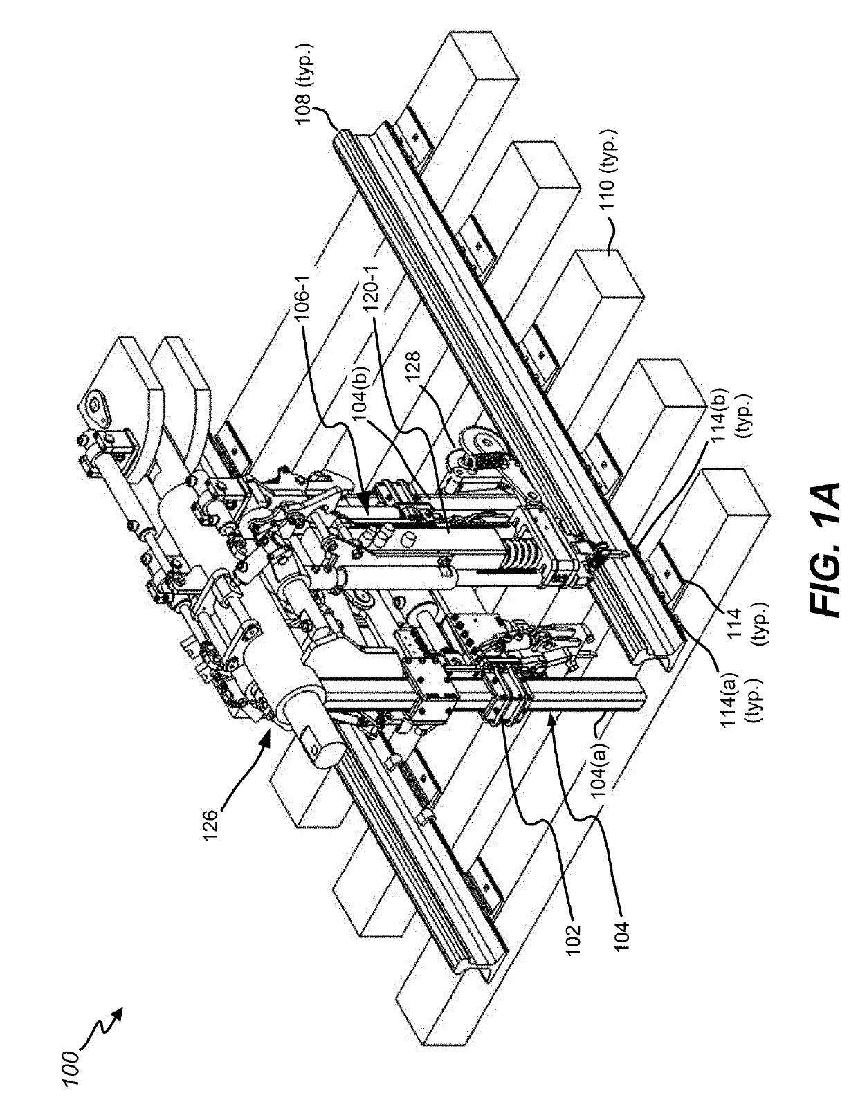
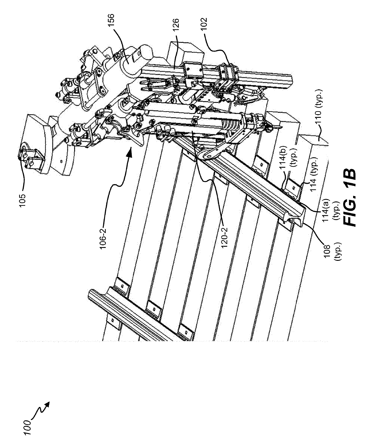
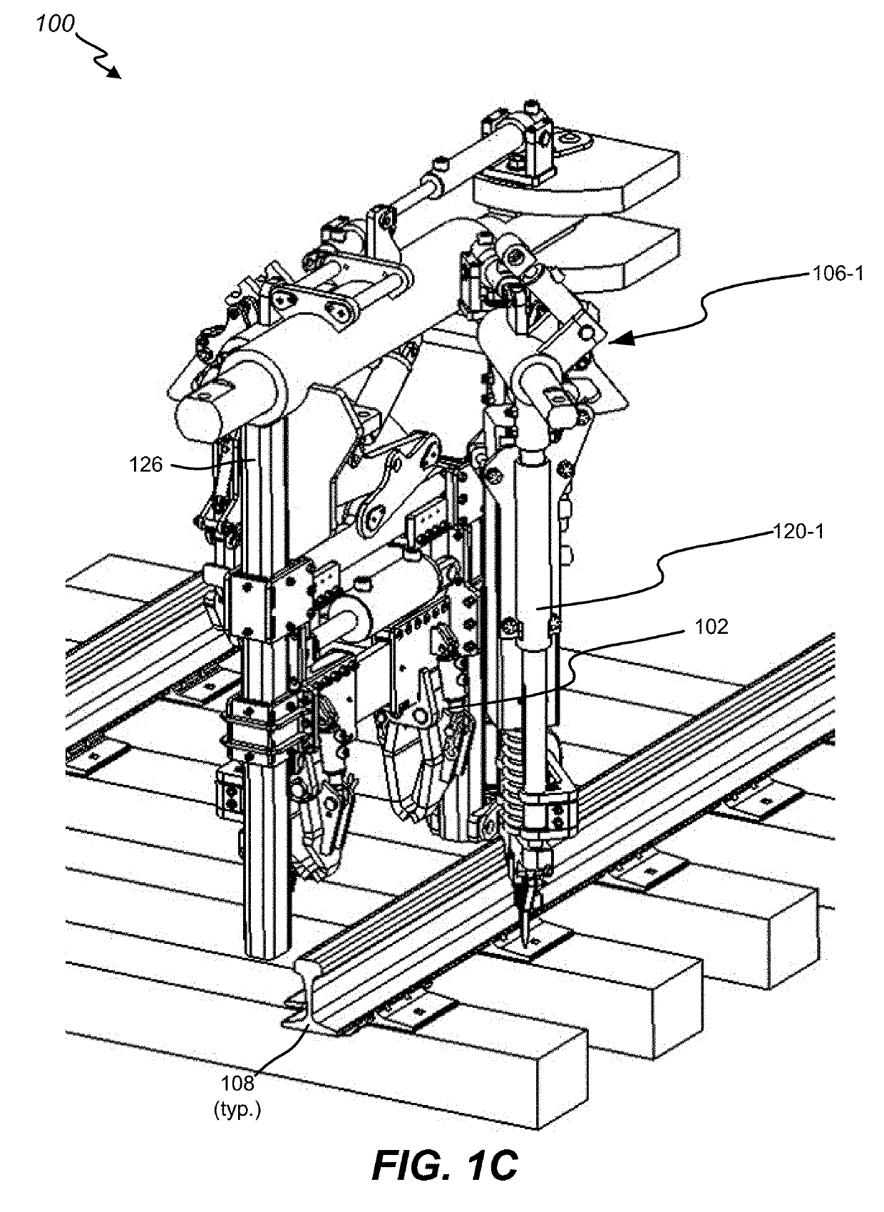
[0049]FIGS. 1A, 1B, and 1C depict perspective views of a portion of a single-plane, multifunctional railway component handling system 100 from a field side of a rail 108, in accordance with disclosed embodiments of the present disclosure. In FIG. 1A, the single-plane, multifunctio...


PUM


Abstract

Systems, methods, and machine-readable media to facilitate installation and adjustment of railway components are disclosed. Aligning of a railway anchor manipulator and a railway fastener installer with respect to a railway tie may be caused. The railway anchor manipulator may be slidably coupled with a frame assembly of a railway workhead, and may include anchor tools. The railway fastener installer may be slidably coupled with the main shaft structure, may include a hammer assembly, and may be operable to install railway fasteners through holes of a railway tie plate. The railway fastener installer may be caused to install the railway fasteners. The railway anchor manipulator may be lowered to a deployed position, and railway anchors may be adjusted with the anchor tools.

Description

CROSS-REFERENCE TO RELATED APPLICATION[0001]The present application claims the benefit of, and priority to, U.S. Provisional Application No. 62 / 610,467, filed on Dec. 26, 2017, by Hamilton et al. and entitled “Adaptive Railway Fastener and Anchor Installation System,” the entire disclosure of which is incorporated herein by reference for all purposes.BACKGROUND[0002]Disclosed embodiments of the present disclosure relate generally to railways, and in particular to maintenance of way with systems, apparatuses, and methods for railway component installation.[0003]With the hundreds of thousands of miles of railroad track traversing the United States alone, in addition to the great lengths throughout other countries of the world, maintenance of way is a tremendous and important effort. One aspect of maintenance of way is railway tie maintenance. Railway ties are typically made of wood or other materials that age and deteriorate over time due to railway use and environmental conditions. A...

Claims


Application Information

Patent Timeline
Patent Type & Authority Applications(United States)
IPC IPC(8): E01B29/26E01B35/10
CPCE01B29/26E01B35/10E01B2201/04E01B29/32
Inventor HAMILTON, WILLIAM MICHAELKOCI, RYAN JAYTOMAC, JUSTIN WYNNE
Owner MOW EQUIP SOLUTIONS INC
Why Eureka
Try Eureka