Monitoring apparatus for battery cells

Active Publication Date: 2019-06-27
DENSO CORP
View PDF3 Cites 6 Cited by
  • Summary
  • Abstract
  • Description
  • Claims
  • Application Information

AI Technical Summary

Benefits of technology

The invention described in this patent text eliminates the problem of noise interference in a battery monitoring circuit. By increasing the distance between the noise removal elements and the electrode terminal-side ends of the wiring patterns, noise is prevented from reaching the monitoring circuit. This ensures accurate monitoring of battery cell voltages and prevents the monitoring circuit's accuracy from being lowered due to noise.

Problems solved by technology

Therefore, when noise is inputted to the voltage detection lines, it may become impossible for the battery ECU to accurately detect the voltages.
As a result, it is possible to suppress the accuracy of the monitoring of the voltages of the battery cells by the monitoring circuit from being lowered due to noise.

Method used


Image

  • Monitoring apparatus for battery cells
  • Monitoring apparatus for battery cells
  • Monitoring apparatus for battery cells

Examples


first embodiment

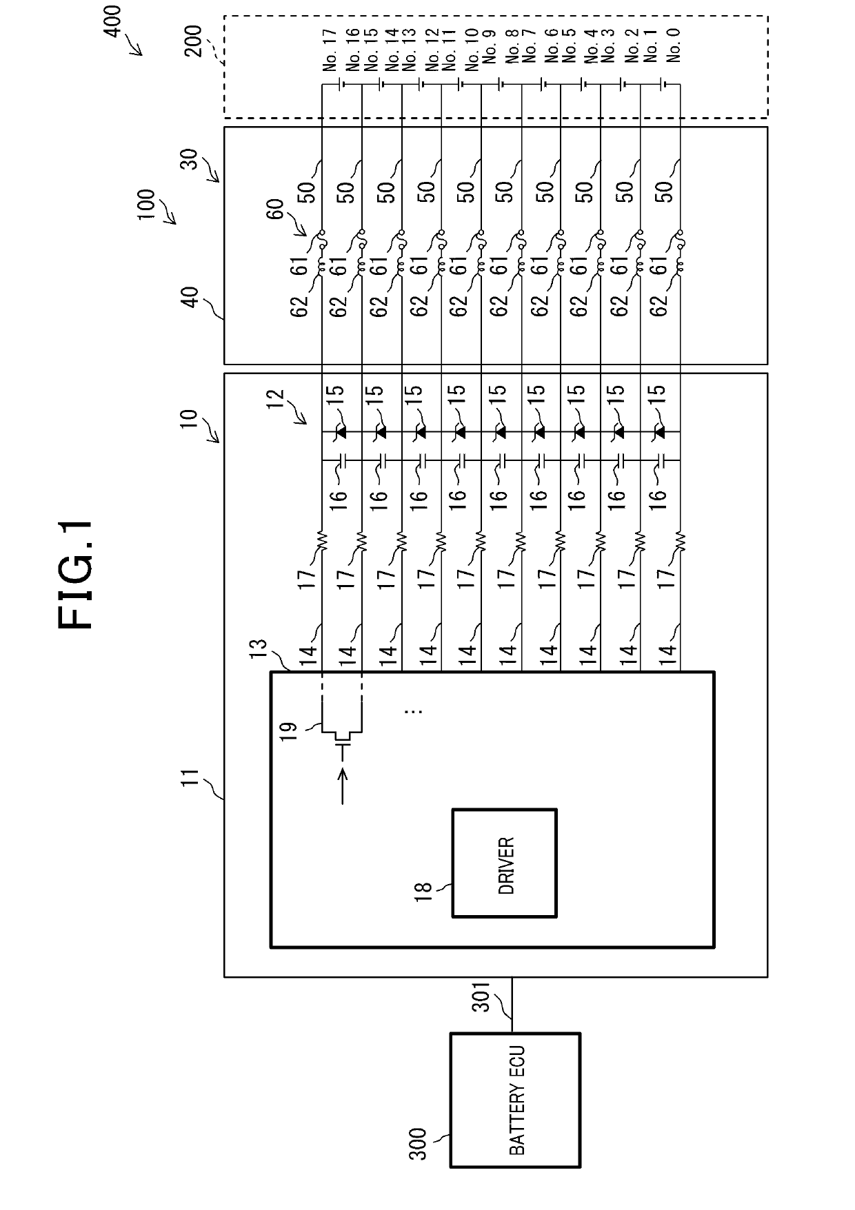
[0026]A monitoring apparatus 100 according to the first embodiment and a battery pack 400 which includes the monitoring apparatus 100 will be described hereinbelow with reference to FIGS. 1-6.

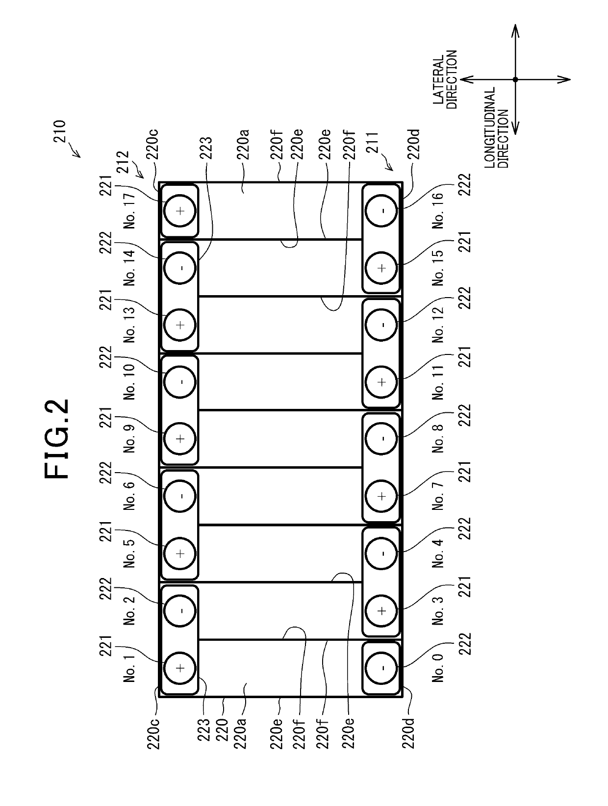
[0027]For the sake of convenience of explanation, hereinafter, three mutually perpendicular directions of the battery pack 400 will be respectively referred to as the lateral direction, the longitudinal direction and the height direction.

[0028]In the present embodiment, the battery pack 400 is designed to be used in, for example, a hybrid vehicle. In this case, the lateral direction of the battery pack 400 coincides with the longitudinal direction (or forward-backward direction) of the hybrid vehicle. The longitudinal direction of the battery pack 400 coincides with the lateral direction (or left-right direction) of the hybrid vehicle. The height direction of the battery pack 400 coincides with the height direction of the hybrid vehicle. In addition, when the hybrid vehicle is parked on a horiz...

first modification

[First Modification]

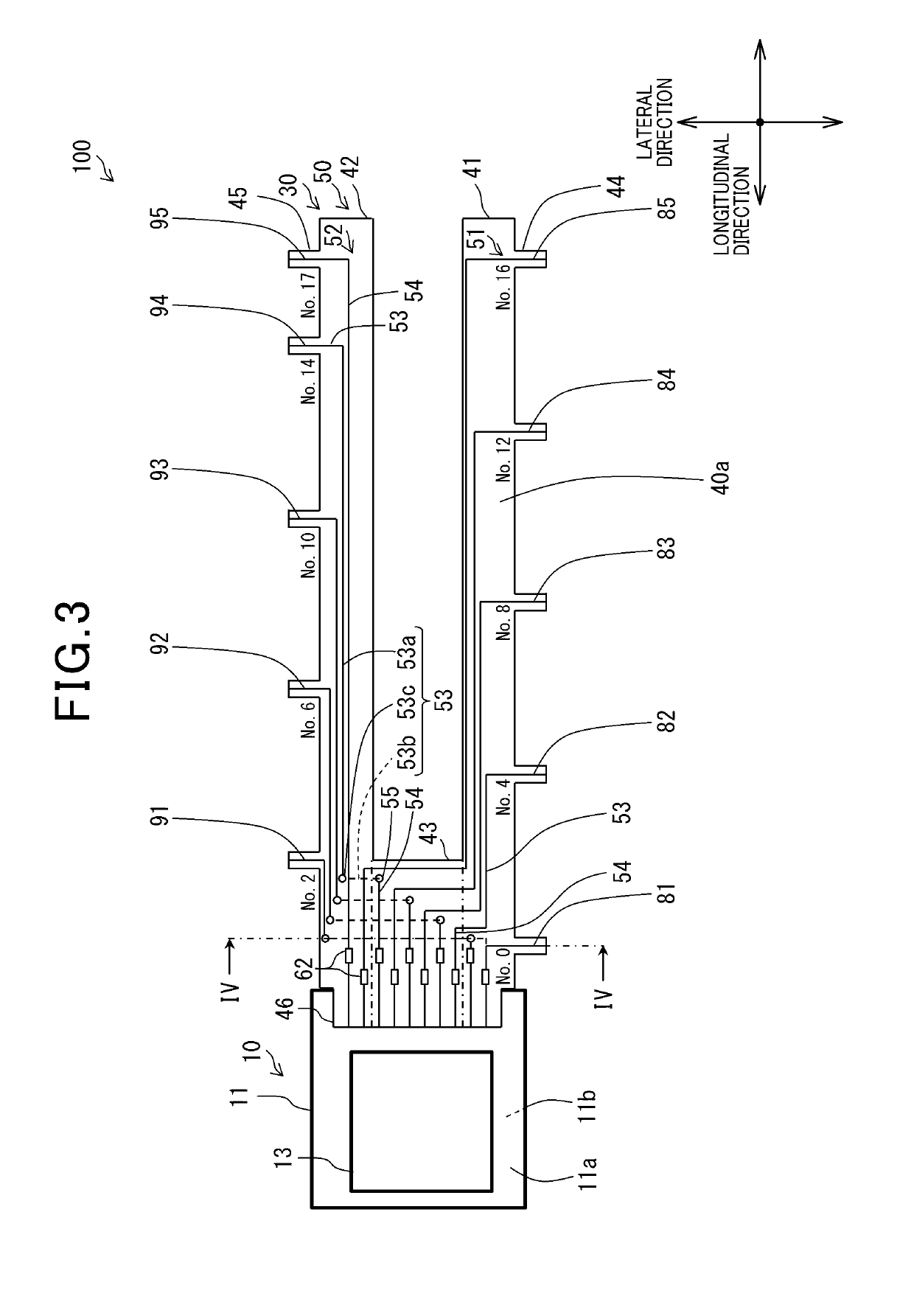
[0157]In the previous embodiment, in each of the first to the fourth upper wiring patterns 91-94, part of the first wiring 53 is formed as the back wiring 53b on the back surface 40b of the flexible substrate 40. Moreover, the entire fifth upper wiring pattern 95 is formed on the front surface 40a of the flexible substrate 40 (see FIG. 3).

[0158]In contrast, in this modification, as shown in FIG. 7, in each of the first to the fourth upper wiring patterns 91-94, the entire first wiring 53 is formed as the back wiring 53b on the back surface 40b of the flexible substrate 40. Consequently, it becomes unnecessary to provide an internal wiring 53c as shown in FIG. 4 in each of the first to the fourth upper wiring patterns 91-94. As a result, it becomes possible to simplify the manufacturing process of the flexible substrate 40.

[0159]Moreover, in this modification, in the fifth upper wiring pattern 95, the first wiring 53 is formed on the back surface 40b of the flexib...

second modification

[Second Modification]

[0160]In the previous embodiment, all the second wirings 54 of the lower wiring patterns 81-85 and upper wiring patterns 91-95 are arranged from the lower side to the upper side in the lateral direction in order of increasing electric potential (see FIG. 3).

[0161]In contrast, in this modification, as shown in FIG. 8, all the second wirings 54 of the lower wiring patterns 81-85 and upper wiring patterns 91-95 are arranged from the lower side to the upper side in the lateral direction in order of decreasing electric potential.

[0162]Moreover, in this modification, in each of the first to the fourth lower wiring patterns 81-84 and the fifth upper wiring pattern 95, part of the first wiring 53 is formed as a back wiring 53b on the back surface 40b of the flexible substrate 40.

[0163]In addition, though not shown in the figures, it may be possible to: (1) form, for each of the first wiring patterns 51, part of the first wiring 53 of the first wiring pattern 51 on one o...


PUM


Abstract

A monitoring apparatus is provided for monitoring voltages of a plurality of battery cells. The battery cells are electrically connected in series with each other and each include a pair of electrode terminals. The monitoring apparatus includes a flexible substrate, a monitoring circuit and a plurality of noise removal elements. The flexible substrate has a plurality of wiring patterns formed thereon. The wiring patterns are electrically connected with the electrode terminals of the battery cells. The monitoring circuit is electrically connected with the electrode terminals of the battery cells via the wiring patterns and configured to monitor the voltages of the battery cells inputted thereto via the wiring patterns. The noise removal elements are provided in monitoring circuit-side parts of the wiring patterns to remove noise inputted to the wiring patterns.

Description

CROSS-REFERENCE TO RELATED APPLICATION[0001]This application is based on and claims priority from Japanese Patent Application No. 2017-247990 filed on Dec. 25, 2017, the contents of which are hereby incorporated by reference in their entirety into this application.BACKGROUND1 Technical Field[0002]The present disclosure relates to monitoring apparatuses for monitoring voltages of battery cells.2 Description of Related Art[0003]Japanese Patent Application Publication No. JP2017027831A discloses a battery wiring module that includes a plurality of connecting members (or busbars) and a flexible printed board (or FPC). Each of the connecting members connects one pair of positive and negative electrode terminals of different battery cells. The flexible printed board has a plurality of voltage detection lines formed thereon. Each of the voltage detection lines has a first end connected to one of the connecting members and a second end connected to a connector. The connector is connected to...

Claims


Application Information

Patent Timeline
IPC IPC(8): H01M10/48H01M2/34G01R31/382H01M50/51H01M50/569
CPCH01M10/482H01M2/348G01R31/382G01R19/0084H01M50/51H01M50/569G01R31/396G01R31/3835H01M10/425Y02E60/10H01M50/581
Inventor TANABE, YASUHITOKUBO, SYUNICHI
Owner DENSO CORP
Why Eureka
Try Eureka