Connector

a technology of connecting rods and connectors, applied in the direction of coupling contact members, coupling device connections, securing/insulating coupling contact members, etc., can solve the problems of affecting the reliability of terminal fittings, affecting the flow of current, and difficulty in applying to terminal fittings that must have electrical reliability, so as to achieve enhanced electrical reliability, restrict insertion, and enhance electrical reliability

a technology of connecting rods and connectors, applied in the direction of coupling contact members, coupling device connections, securing/insulating coupling contact members, etc., can solve the problems of affecting the reliability of terminal fittings, affecting the flow of current, and difficulty in applying to terminal fittings that must have electrical reliability, so as to achieve enhanced electrical reliability, restrict insertion, and enhance electrical reliability

US20190199008A1Active Publication Date: 2019-06-27SUMITOMO WIRING SYST LTD

Image

  • Connector
  • Connector
  • Connector

Examples


Embodiment Construction

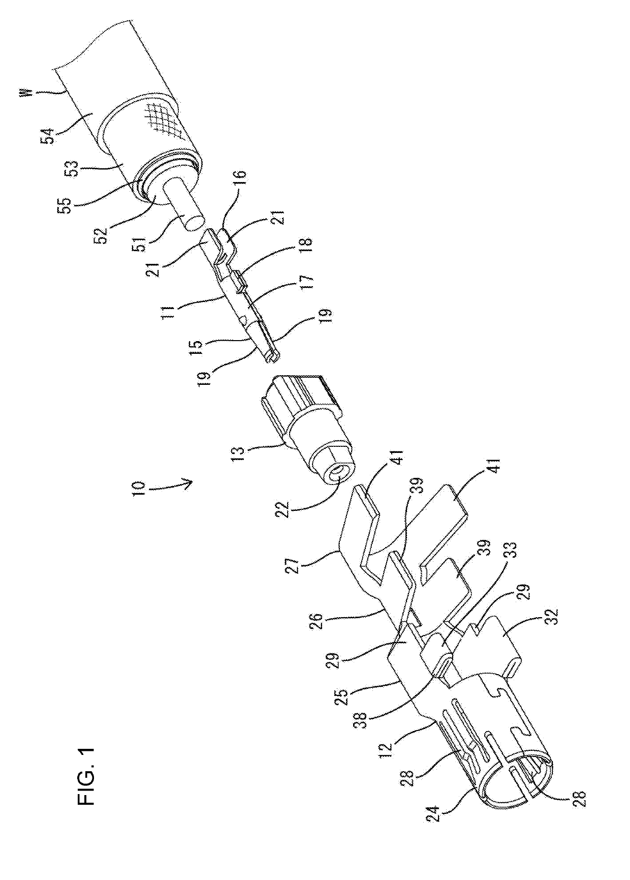
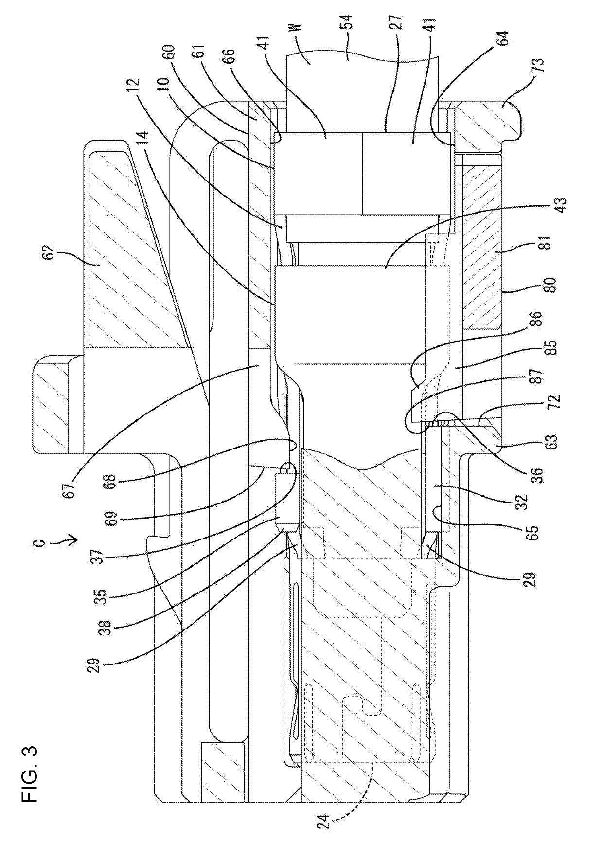
[0025]One embodiment is described with reference to FIGS. 1 to 11. A connector C according to this embodiment includes a terminal fitting 10, a housing 60 for accommodating the terminal fitting 10 and a retainer 80 to be mounted movably into the housing 60. The housing 60 is connectable to an unillustrated mating housing. Note that, in the following description, a side of the housing 60 facing the mating housing at the start of connection is referred to as a front concerning a front-rear direction. A vertical direction is based on figures except FIGS. 7 and 11.

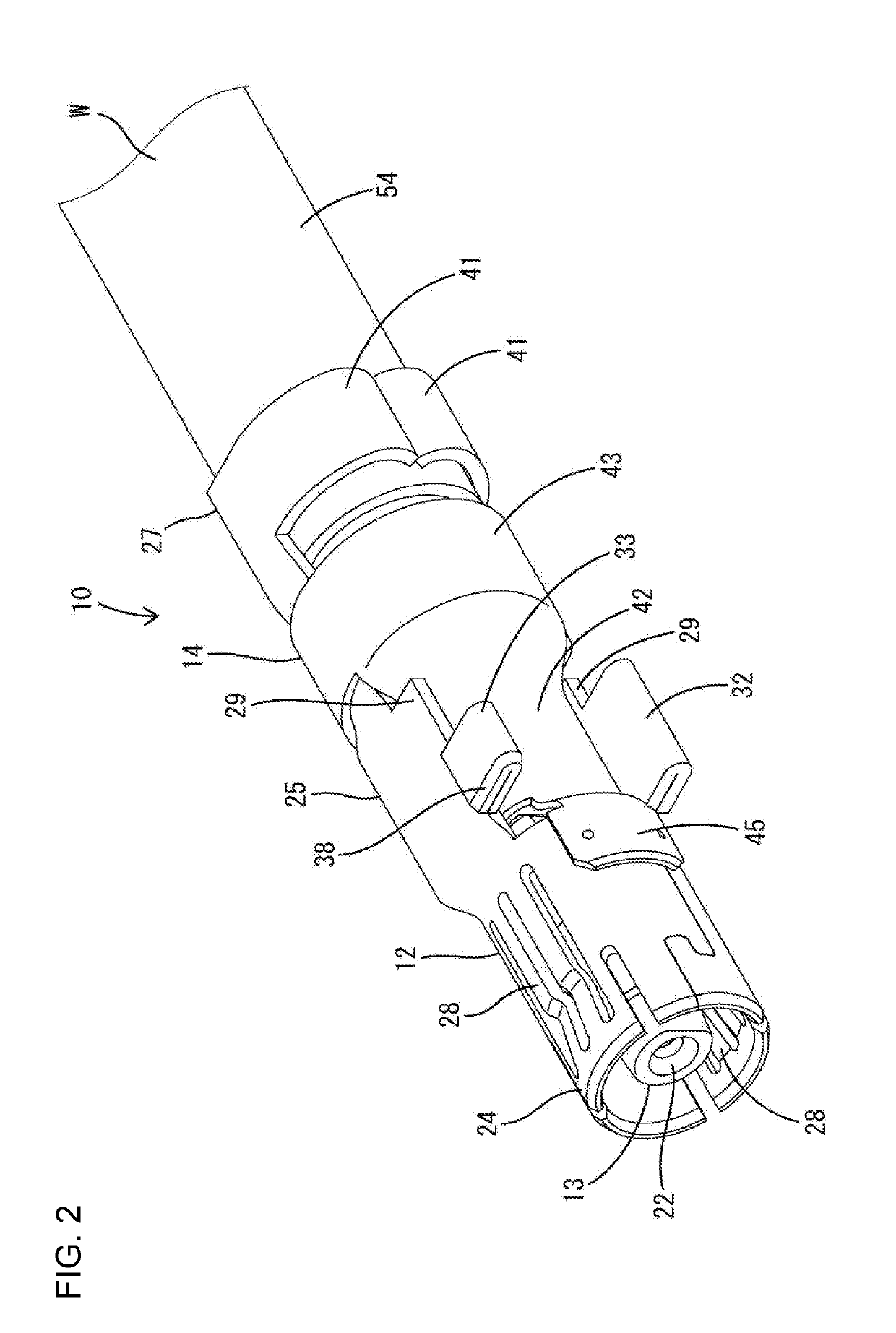
[0026]As shown in FIG. 2, the terminal fitting 10 is connected to an end part of a shielded cable W and includes an inner conductor 11 (see FIG. 1), an outer conductor 12, a dielectric 13 and a cover 14. The inner conductor 11, the outer conductor 12 and the cover 14 are made of a conductive metal, and the dielectric 13 is made of an insulating synthetic resin.

[0027]As shown in FIG. 1, the shielded cable W is a so-called coaxi...


PUM


Abstract

A connector (C) includes a housing (60), a terminal fitting (10) and a retainer (80). The housing (60) includes a cavity (64) extending in a front-rear direction and a retainer insertion hole (72) intersecting and communicating with the cavity and open in an outer surface. The terminal fitting (10) is inserted into the cavity (64) from behind, and a stabilizer configured to guide an inserting operation into the cavity (64) and restrict the inserting operation in an erroneous posture projects on an outer side. The retainer (80) is inserted into the retainer insertion hole (72) and include a retaining portion (85) configured to face the stabilizer from behind.

Description

BACKGROUNDField of the Invention[0001]The invention relates to a connector.Related Art[0002]Japanese Patent No. 6235199 discloses a connector with a connector housing, a terminal and a retainer. The connector housing includes a terminal accommodation chamber and a retainer insertion hole intersecting and communicating with the terminal accommodation chamber. The terminal is composed of a mating terminal connecting portion and a wire connecting portion that are joined by a linking portion.[0003]The retainer is inserted into the retainer insertion hole and is movable from a terminal insertion allowance position to a terminal connection position. In assembling, the retainer is set at the terminal insertion allowance position and the terminal is inserted into the terminal accommodation chamber. The terminal is retained in the terminal accommodation chamber primarily by being locked by a flexible locking lance of the connector housing. The retainer then is moved from the terminal inserti...

Claims


Application Information

Patent Timeline
27 Jun 2019
Publication
US20190199008A1
IPC
H01R4/18; H01R13/639; H01R9/05; H01R13/6582; H01R24/40; H01R13/436; H01R13/50
CPC
H01R4/185; H01R13/639; H01R9/05; H01R13/6582; H01R24/40; H01R13/4362; H01R13/50; H01R13/42
Inventors
KANEMURA, KEISUKE; MITSUI, SHOHEI