Hand-Operated Spreader

Active Publication Date: 2019-07-04
SK & Y AGRI EQUIP
View PDF0 Cites 6 Cited by
  • Summary
  • Abstract
  • Description
  • Claims
  • Application Information

AI Technical Summary

Benefits of technology

[0007]An objective of present invention is to provide a hand-operated

Problems solved by technology

However, it is not difficult to find that there are some shortcomings in the conventional structure.
The main reasons are as follows: (1) When the seeds fall through the discharge hole 81 of the container 80 and lay on the supply tray 78, the supply tray 78 is flat without a guiding effect and lacks a stirring mechanism, resulting in easy occurrence of accumulated effect due to moisture or heavy pressure, which can not be effectively discharged through the feeding aperture 79.
On the o

Method used


Image

  • Hand-Operated Spreader
  • Hand-Operated Spreader
  • Hand-Operated Spreader

Examples


Example

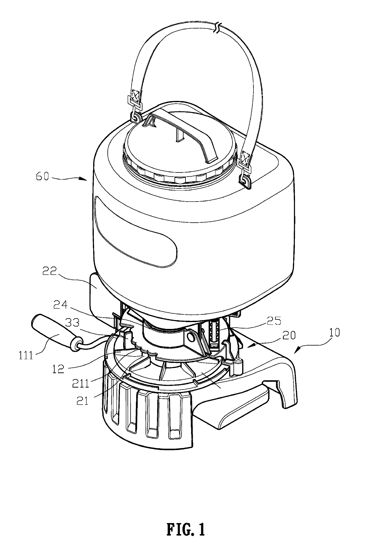
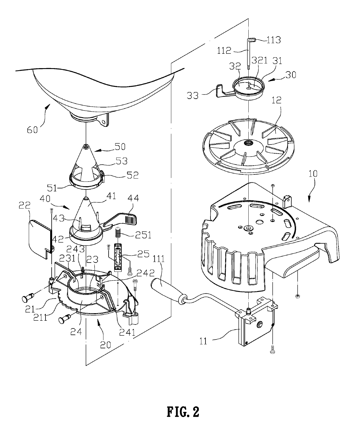
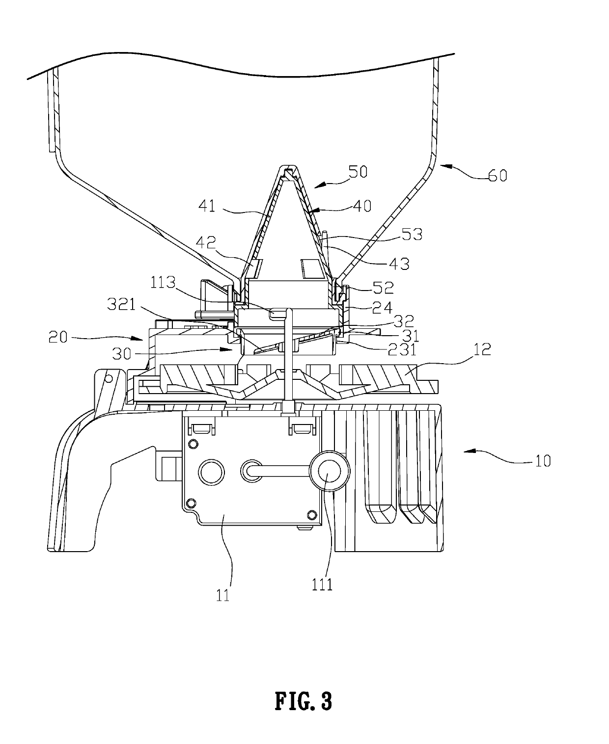
[0022]First, please refer to FIG. 1 and FIG. 2, a hand-operated spreader comprises a base 10, an assembly member 20, a feeding rudder 30, an adjusting member 40, and a feeding cone 50. The base 10 is provided with a transmission mechanism 11 with an arm 111, and a rotating disk 12 connected to the transmission mechanism 11, and the transmission mechanism 11 is drives the rotating disk 12 through a central shaft 112. The assembly member 20 is mounted on the base 10 above the rotating disk 12 and one side of the assembly member 20 is provided with an open end 21 for discharging objects during rotation of the rotating disk 12. A protective barrier 22 is pivotally provided on one side of the open end 21 to prevent spilled material. The open end 21 is further provided with a continuous wave-shaped limiting portion 211, the assembly member 20 is centrally provided with a feeding opening 23, a circular sidewall 24 is arranged upwards from the feeding opening 23, and more than one engaging ...


PUM


Abstract

A hand-operated spreader has a base, an assembly member, a feeding rudder, an adjusting member, a feeding cone and a container. The feeding cone has the effect of guiding along the cone through the conical body to prevent the feeding aperture from clogging due to moisture, accumulation or weight. The feeding rudder is mounted on the feeding opening of the assembly member and is driven by the rotating handle on one side, and the rotating handle may set the spreading direction along the limiting portions of the open end, which enables the feeding rudder to be reliably positioned via the limiting portion and prevent the feeding rudder from being unstable while improving the dropout accuracy of the discharged material.

Description

BACKGROUND OF THE INVENTION1. Field of the Invention[0001]The present invention relates to a seed spreader structure, and more particularly to a hand-operated seed spreader.2. Description of the Related Art[0002]Referring to FIGS. 9 and 10, a conventional seed spreader includes a base 70 associated with a transmission mechanism 72 having an arm 71. The base 70 is provided with a rotating shaft 73 connected to the transmission mechanism 72, and the rotating shaft 73 engages with a rotating disk 74. The base 70 is combined with a cover 75 for receiving all the above components. A rudder member 76 having a through aperture 762 disposed on an inclined surface 761 is provided above the center of the cover 75. A control plate 77 and a supply plate 78 are stacked over the rudder member 76, wherein the supply plate 78 is disposed on top of the control plate 77 and locked with the cover 75. The control plate 77 is rotatable on the cover 75, and the feeding aperture 79 are disposed misaligned...

Claims


Application Information

Patent Timeline
IPC IPC(8): A01C7/02
CPCA01C7/02A01C17/006A01C17/008
Inventor WU, JUI-CHANG
Owner SK & Y AGRI EQUIP
Why Eureka
Try Eureka