

Dynamic LCD Screen
- Summary
- Abstract
- Description
- Claims
- Application Information
AI Technical Summary
Benefits of technology
Problems solved by technology
Method used
Image

Examples
Example
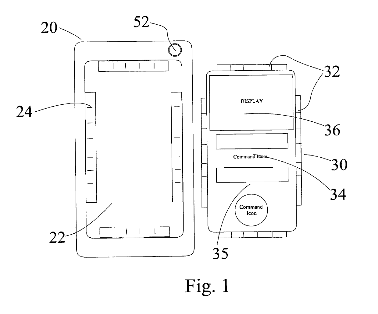
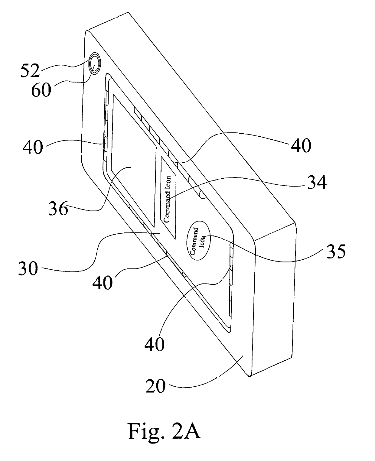
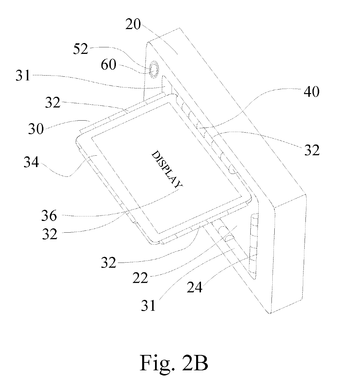
DRAWING NUMERALS
[0022]10 PED[0023]20 Case[0024]22 Case Bed[0025]24 Case Coupling Mechanism[0026]30 LCD Remote[0027]31 Periphery Sidewall[0028]32 Screen Coupling Mechanism[0029]34 Control Interface[0030]35 Command Icons[0031]36 Image Display[0032]40 Operative Hinge[0033]52 Lens Opening[0034]54 Base Device Interface[0035]56 Base Device Display[0036]58 Base Command Icon[0037]60 Back Facing Camera Lens[0038]62 Front Facing Camera Lens[0039]72 Command Data[0040]74 Image Data[0041]80 Vertical Axis[0042]82 Horizontal Axis
DETAILED DESCRIPTION OF DRAWINGS
[0043]FIG. 1 shows a dynamic LCD remote 30 detached from a protective case 20. The exemplary case 20 is configured to receive and securely couple a smartphone or other PED. Flexural rigidity, snap-hooking, clamping, or any other coupling means known in the art may be utilized. The case is composed of polycarbonate, rubber, elastomeric or other durable material permitting shock absorption and augmenting protection of the coupled device. The c...
PUM
 Abstract
Description
Claims
Application Information