Protection circuit for decoupling a low voltage circuitry from a high voltage circuitry

a protection circuit and low voltage technology, applied in logic circuit interface arrangements, logic circuit coupling/interface arrangements, and arrangements responsive to excess voltage, etc., can solve problems such as electrical overstress (eos) and damage to one or more components of low voltage circuitry

Active Publication Date: 2019-07-04
INTEL CORP
View PDF3 Cites 3 Cited by
  • Summary
  • Abstract
  • Description
  • Claims
  • Application Information

AI Technical Summary

Problems solved by technology

Without proper protection, the high voltage from the high voltage circuitry may propagate to the low voltage circuitry, thereby gene...

Method used


Image

  • Protection circuit for decoupling a low voltage circuitry from a high voltage circuitry
  • Protection circuit for decoupling a low voltage circuitry from a high voltage circuitry
  • Protection circuit for decoupling a low voltage circuitry from a high voltage circuitry

Examples


example 1

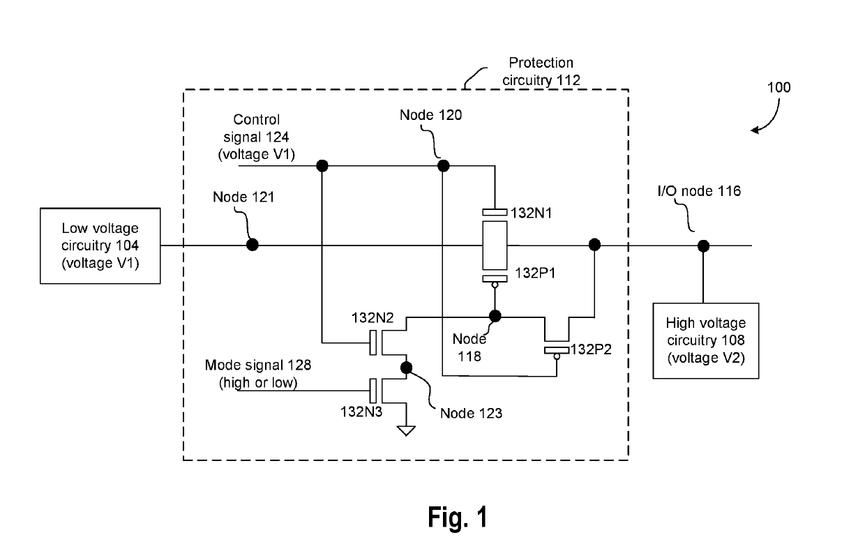
[0075]An apparatus comprising: a node; and a protection circuitry coupled between: the node and a first circuitry that is to selectively output a first voltage, wherein the node is coupled to a second circuitry that is to selectively output a second voltage, wherein the protection circuitry comprises: a pair of complementary parallel transistors coupled between the node and the first circuitry, the pair comprising first and second transistors, wherein a gate of the first transistor is to receive a control signal at the first voltage, and a third transistor to selectively couple a gate of the second transistor to the node, a gate of the third transistor to receive the control signal at the first voltage.

example 2

[0076]The apparatus of example 1 or any other example, wherein the protection circuitry comprises: a fourth transistor and a fifth transistor in series, wherein the fourth and fifth transistors are to selectively couple the gate of the second transistor to a ground terminal.

example 3

[0077]The apparatus of example 2 or any other example, wherein: a gate of the fourth transistor is to receive the control signal at the first voltage.


PUM


Abstract

An apparatus is provided which comprises: a protection circuitry coupled between: a node and a first circuitry that is to selectively output a first voltage, the node coupled to a second circuitry that is to selectively output a second voltage, the protection circuitry comprising: a pair of complementary parallel transistors coupled between the node and the first circuitry, the pair comprising first and second transistors, wherein a gate of the first transistor is to receive a control signal at the first voltage, and a third transistor to selectively couple a gate of the second transistor to the node, a gate of the third transistor to receive the control signal at the first voltage.

Description

BACKGROUND[0001]Often times, an Input / Output (I / O) node may receive a relatively high voltage from a high voltage circuitry, and receive a relatively low voltage from a low voltage circuitry, e.g., in a time multiplexed manner. Without proper protection, the high voltage from the high voltage circuitry may propagate to the low voltage circuitry, thereby generating Electrical Overstress (EOS) in the low voltage circuitry, and possibly damaging one or more components of the low voltage circuitry.BRIEF DESCRIPTION OF THE DRAWINGS[0002]The embodiments of the disclosure will be understood more fully from the detailed description given below and from the accompanying drawings of various embodiments of the disclosure, which, however, should not be taken to limit the disclosure to the specific embodiments, but are for explanation and understanding only.[0003]FIG. 1 illustrates a device comprising a protection circuitry to prevent Electrical Overstress (EOS) to a low voltage circuitry, where...

Claims


Application Information

Patent Timeline
IPC IPC(8): H02H3/20H03K19/0175
CPCH02H3/20H03K19/017509H02H3/003
Inventor GAN, KIM SIM
Owner INTEL CORP
Why Eureka
Try Eureka