Liquid cooling device combined on graphics card

a cooling device and graphics card technology, applied in the field of liquid cooling devices, can solve the problems of large volume, large possible leakage of working fluid from gaps formed between any connected components, so as to reduce the number of connecting parts, reduce the probability of working fluid leakage, and reduce the volume of a liquid cooling system

Active Publication Date: 2019-07-04
COOLER MASTER CO LTD
View PDF20 Cites 7 Cited by
  • Summary
  • Abstract
  • Description
  • Claims
  • Application Information

AI Technical Summary

Benefits of technology

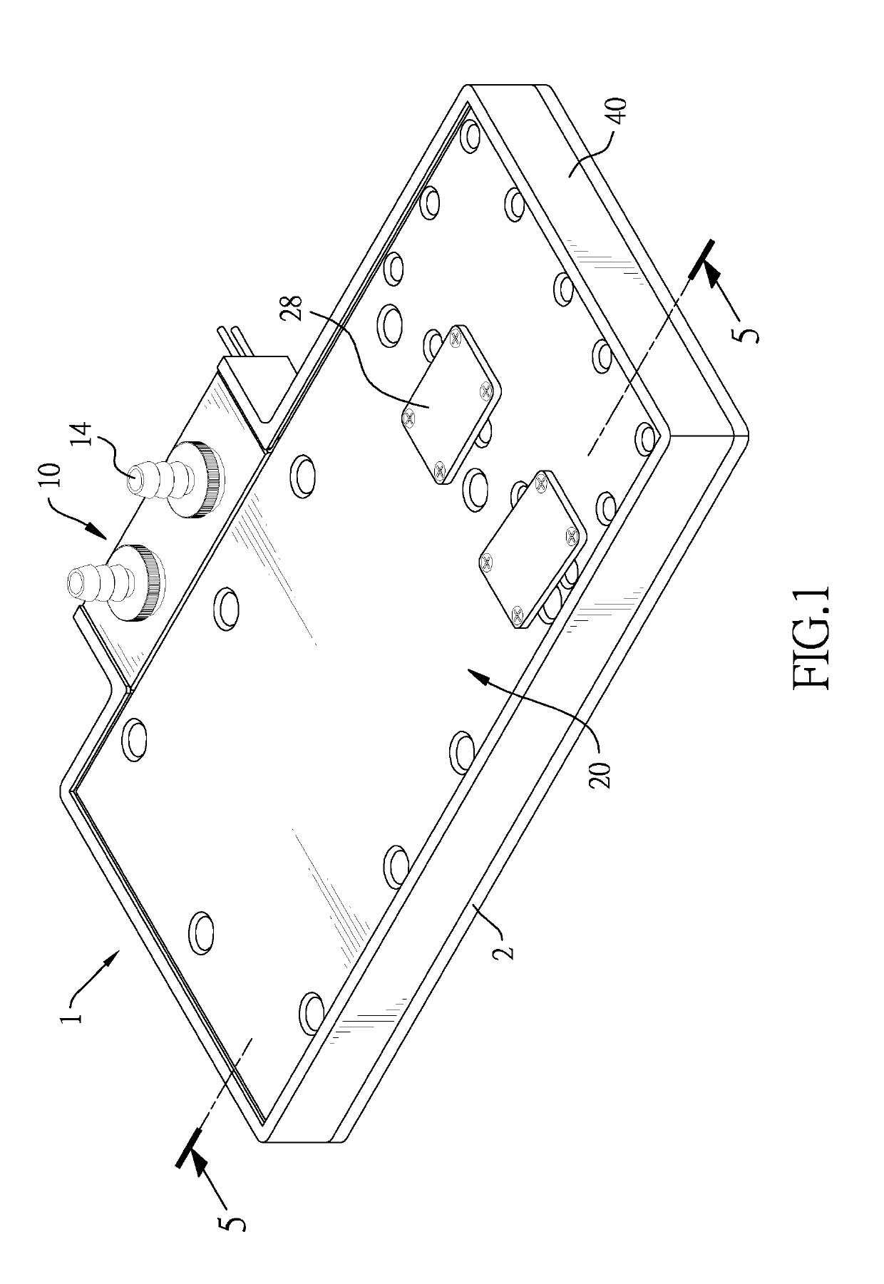
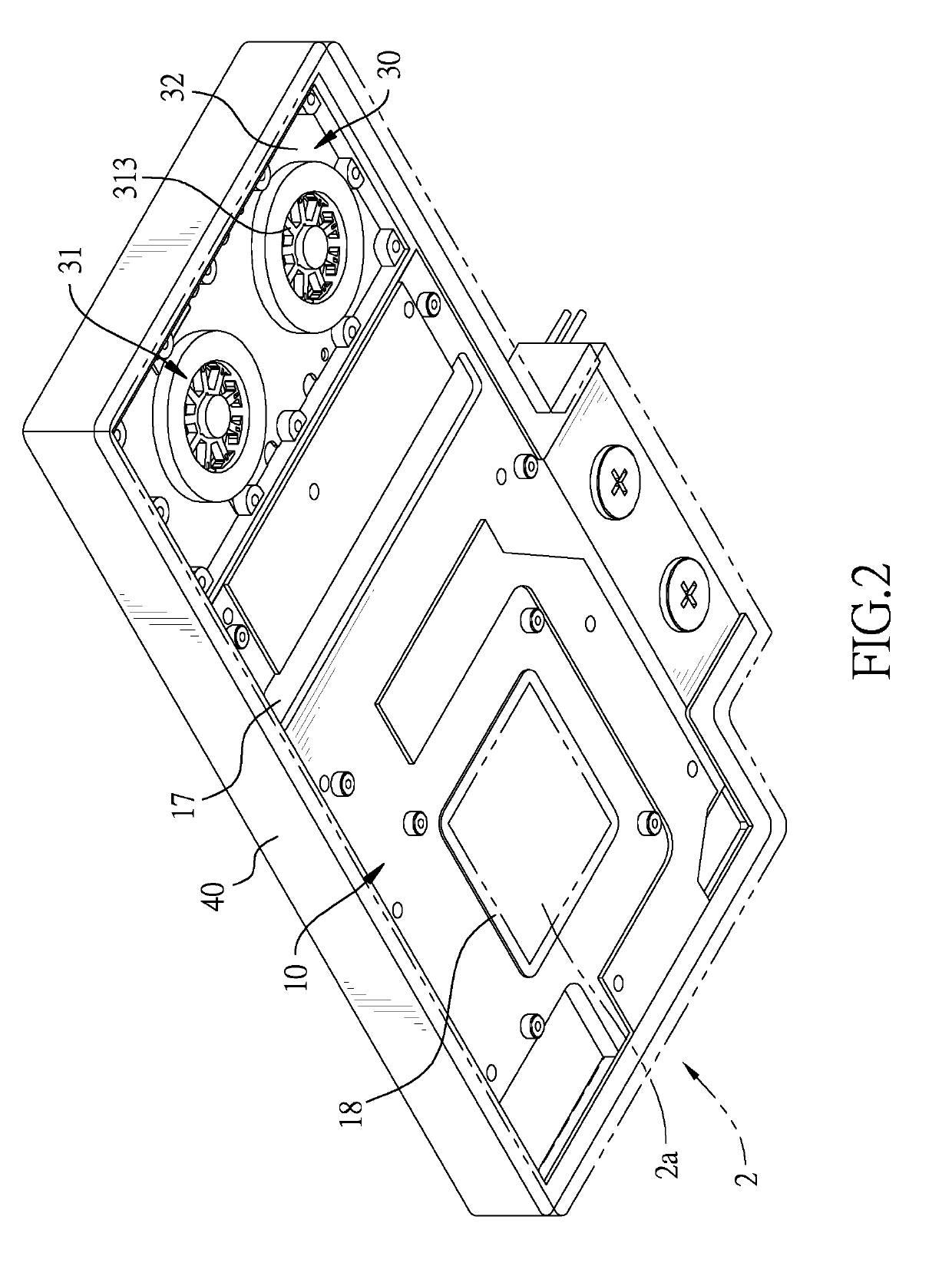
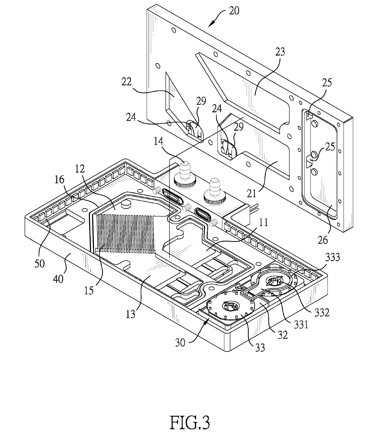
[0010]Functions of the conventional water block and the conventional pump are integrated as the liquid cooling device of the present invention, which reduces an amount of connecting parts and thereby a probability of leakage of the working fluid is also reduced. Furthermore, with the pump assembly, the liquid cooling device of the present invention does not need to be connected to an extra pump, which reduces a volume of a liquid cooling system equipped with the liquid cooling device of the present invention. In addition, with the pump assembly, a thickness of the liquid cooling device of the present invention is decreased enough and thereby the liquid cooling device with a graphics card main body can be mounted in a slot of the computer.

Problems solved by technology

One of the common problems about the conventional liquid cooling system is the working fluid may be leaked from a gap formed between any connected two components, e.g. a gap may be formed between an end of one of the circling pipes and the water block.
Because the heat source may be an electronic component and the working fluid may be water, if the working fluid is leaked, the electronic component may be broken.
One cause of the leak of the working fluid is that the circling pipes cannot sustain high temperature, and thus the circling pipes may become brittle and split itself Another cause of the leak the working fluid is that the circling pipes are not fixed completely on another component.
Another common problem about the conventional liquid cooling system is the entire volume is large.
Precisely, the pump of the liquid cooling system occupies large space, so the entire volume of the liquid cooling system is hard to be reduced.

Method used


Image

  • Liquid cooling device combined on graphics card
  • Liquid cooling device combined on graphics card
  • Liquid cooling device combined on graphics card

Examples


second embodiment

[0056]In the second embodiment, with the at least one groove 17A for stepping aside from electronic components 2b of a graphics card main body 2, a protrusion portion may be formed in an inner surface of the plate 10A and the protrusion portion is corresponding to the groove 17A in location, which causes flowing paths of the working fluid in the liquid cooling device of the present invention to be restricted in width or thickness. To assure the flowing paths are wide or thick enough so that resistances in the flowing paths are low, inner walls of the stepping openings 27A surround said protrusion portion of the plate 10A. In other words, the stepping openings 27A correspond to the groove 17A in location. Therefore, a flowing space is formed between the pad 28A, the stepping openings 27A, and said protrusion portion of the plate 10A.

third embodiment

[0057]Then please refer to FIGS. 14 and 15, which show a third preferred embodiment of the present invention. Technical features of the second preferred embodiment are similar to the aforementioned preferred embodiments and one of the differences is that the protrusion portions of the plate 10B is as thin as possible so the width or thickness of the flowing paths is enough. Therefore, in the third embodiment, the cover 20B does not have any pad as the aforementioned embodiments.

[0058]In another embodiment, the liquid cooling device may only have the first cavity 11, the second cavity 12, and the third cavity 13, or, alternatively, may only have the fourth cavity 21, the fifth cavity 22, and the sixth cavity 23. Therefore, the first space, the second space, and the third space may only be formed respectively by the first cavity 11, the second cavity 12, and the third cavity 13, or, alternatively, may only be formed respectively by the fourth cavity 21, the fifth cavity 22, and sixth ...


PUM


Abstract

A liquid cooling device is provided with a heat dissipating assembly and a pump assembly. The heat dissipating assembly has a plate and a cover. The plate has a connecting surface and a sinking surface opposite each other. The connecting surface has a connecting portion configured to attach to a heat source. The sinking surface has multiple fins corresponding to the connecting portion in location. The cover is mounted on the sinking surface. The pump assembly juxtaposes the heat dissipating assembly. A graphics card is also provided. The graphics card has a graphics card main body and the liquid cooling device. Therefore, functions of the conventional water block and the conventional pump are integrated in one liquid cooling device, which reducing an amount of connecting parts and the probability of leakage of the working fluid.

Description

CROSS-REFERENCE TO RELATED APPLICATIONS[0001]This application is based upon and claims priority under 35 U.S.C. 119 from U.S. Provisional Application No. 62 / 612,825 filed on Jan. 2, 2018, which is hereby specifically incorporated herein by this reference thereto.BACKGROUND OF THE INVENTION1. Field of the Invention[0002]The present invention relates to a liquid cooling device, especially to a liquid cooling device for a graphics card.2. Description of the Prior Arts[0003]A conventional liquid cooling system comprises a pump, a reserve tank, a water block, a heat exchanger (i.e. heater core or radiator), circling pipes connecting aforesaid components, and a working fluid circling in aforesaid components. The water block is attached to a heat source and used for removing heat generated by the heat source. When the working fluid flows through the water block, the heat absorbed by the water block is transferred to the working fluid. Then when the working fluid flows through the heat exch...

Claims


Application Information

Patent Timeline
Patent Type & Authority Applications(United States)
IPC IPC(8): H05K7/20G06F1/20F28F3/02
CPCH05K7/20272G06F1/20H05K7/20409F28F3/02H05K7/20263H05K7/20254G06F2200/201
Inventor TSAI, SHUI-FA
Owner COOLER MASTER CO LTD
Why Eureka
Try Eureka