Applicator instruments with inverted handles and triggers, curved shafts, and visible orientation indicia

a technology of inverted handles and triggers, applied in the field of surgical procedures for correcting defects, can solve the problems of reducing lifting abilities, affecting the effect of bowel movement, and generating a large amount of stress on the abdominal wall, and achieving the effect of eliminating the potential risk of binding

Active Publication Date: 2019-07-11
CILAG GMBH INT
View PDF4 Cites 0 Cited by
  • Summary
  • Abstract
  • Description
  • Claims
  • Application Information

AI Technical Summary

Benefits of technology

[0019]In one embodiment, the multi-fire applicator instrument has a series of strap implants or surgical fasteners stored along the length of the shaft. The applicator has a firing system including a pair of flat stampings with tabbed features. One stamping is stationary and the other stamping cycles in distal and proximal directions to facilitate incremental feeding of the surgical fasteners along the length of the shaft. The flat nature of the stampings facilitates assembly and flexibility as the stampings are guided through a curved path. In one embodiment, a pair of long, molded guide components creates the non-linear path of travel with minimal friction and distortion. The molded components are desirably contained within the shaft, which may be a stainless steel cannula.
[0063]In one embodiment, the applicator instrument preferably includes a counter located at an upper end of the handle for indicating the number of surgical fasteners dispensed from and / or remaining in the applicator instrument. In one embodiment, the counter desirably includes a counter window formed at the upper end of the handle, a rotatable disc visible through the counter window, a rotatable gear connected with the rotatable disc and having teeth extending below the rotatable disc, and a lockout counter pivotally secured to the handle for toggling between a forward position and a rear position. The lockout counter preferably has a first tooth that engages the rotatable gear teeth when in the forward position and a second tooth that engages the rotatable gear teeth when in the rear position. The counter preferably includes a lockout counter spring in contact with the lockout counter for normally urging the lockout counter into the forward position. In one embodiment, when the trigger is fully squeezed, the first rotating link contacts the lockout counter for overcoming the force of the lockout counter spring for toggling the lockout counter into the rear position, whereby the first and second teeth of the lockout counter engage the teeth of the rotatable gear for rotating the rotatable disc. The spring member on the lockout counter allows for additional over travel of the rotating link after the counter completes its counting cycle.

Problems solved by technology

Hernias of this type may result from a congenital defect, or may be caused by straining or lifting heavy objects.
Lifting heavy objects can generate a large amount of stress upon the abdominal wall, which may rupture or tear to create the defect or opening.
In any case, the patient may be left with an unsightly bulge of abdominal contents protruding through the defect, which may result in pain, reduced lifting abilities, and in some cases, impaction of the bowel, or possibly other complications if the flow of blood is cut off to the protruding tissue.
These instruments have not gained acceptance by the surgical community, possibly due to their single shot capabilities and the large size of the rotary magazine, which can restrict the use of such an instrument to an open procedure.
Although the Fogelberg et al. references teach a reciprocating feeding mechanism with a single reciprocating member, they do not teach the use of the clip applier in the attachment of hernia mesh, nor do they teach the individual driving or feeding of each clip by a moving member.
Until recently, there were no absorbable tacks available on the market, and surgeons could only use absorbable sutures in order to provide a fixation means that did not permanently stay in the body.
However, using sutures is exceedingly difficult for some repair procedures.
During intra-peritoneal onlay mesh repairs, commonly referred to as Open IPOM, visibility is often very poor.
The incision may be increased to improve visibility at the expense of the cosmesis, however, inside of the abdominal cavity, lighting is often insufficient.
Improper visibility can lead to improper placement of fixation points within a skirted mesh implant.
Improper visibility can also lead to accidental bowel perforation, particularly if a loop of bowel is above the skirted mesh but is not visible.

Method used


Image

  • Applicator instruments with inverted handles and triggers, curved shafts, and visible orientation indicia
  • Applicator instruments with inverted handles and triggers, curved shafts, and visible orientation indicia
  • Applicator instruments with inverted handles and triggers, curved shafts, and visible orientation indicia

Examples


Embodiment Construction

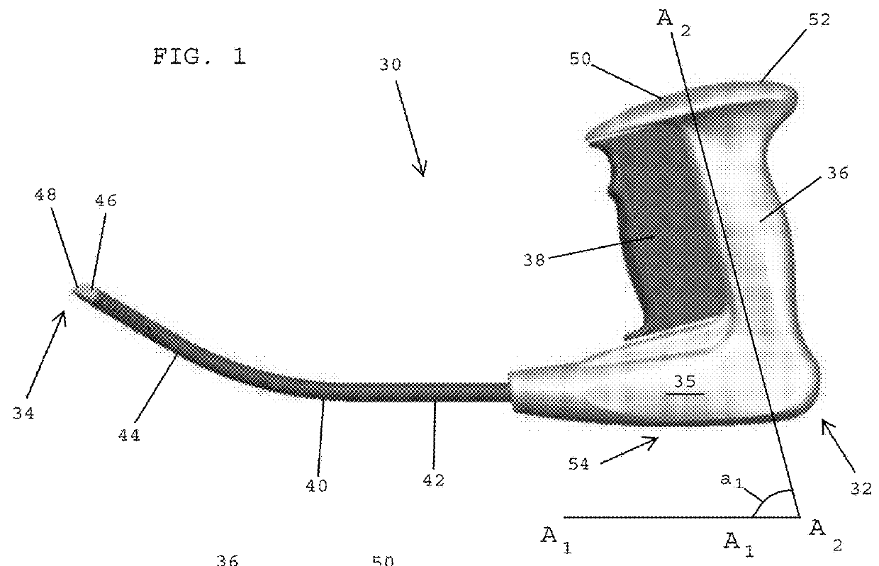
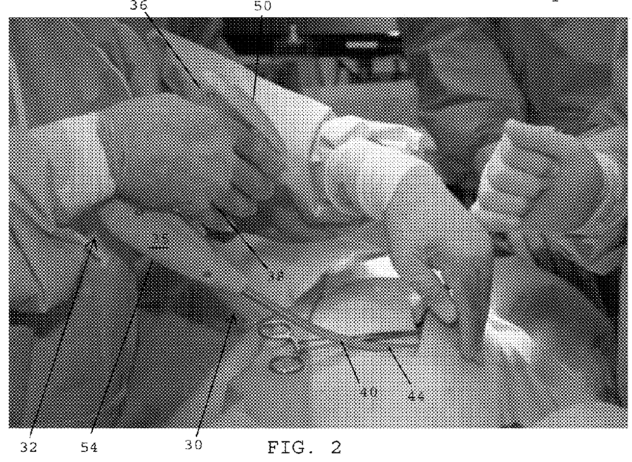
[0131]Referring to FIG. 1, in one embodiment, an applicator instrument 30 for dispensing surgical fasteners has a proximal end 32, a distal end 34, and a longitudinal axis A1-A1 that extends between the proximal and distal ends. The applicator instrument 30 desirably includes a housing 35, a handle 36 extending upwardly from the housing, a trigger 38 mounted on the handle, and an elongated shaft 40 that extends distally from the housing 35. The elongated shaft 40 includes a first section 42 that extends along the longitudinal axis A1-A1 of the applicator instrument, and a second section 44 that is angled or curved relative to the first section 42.

[0132]In one embodiment, a cap 46 is secured to the distal end of the elongated shaft 40. The cap 46 preferably has a distal face 48 that slopes away from a lower distal edge of the cap and toward the proximal end 32 of the applicator instrument 30.

[0133]In one embodiment, the handle 36 includes an upper end 50 containing a counter 52 that ...


PUM


Abstract

An applicator instrument for dispensing surgical fasteners includes a housing, a firing system moveable along a first axis, a handle extending upwardly from the housing along a second axis that defines an acute angle with the first axis, the handle having an upper free end that defines a top of the applicator instrument, a trigger coupled with the housing for activating the firing system, and an elongated shaft extending from the distal end of the housing, the elongated shaft having a proximal shaft section extending along the first axis and a distal shaft section that is oriented at an angle relative to the proximal shaft section for extending upwardly toward the top of the applicator instrument. The trigger is squeezed for dispensing surgical fasteners from the distal end of the elongated shaft. The applicator instrument has at least one visual indicator for indicating a proper orientation for the applicator instrument in which the upper free end of the handle is positioned above the housing.

Description

CROSS REFERENCE TO RELATED APPLICATIONS[0001]The present patent application is a continuation of U.S. patent application Ser. No. 13 / 720,198, filed on Dec. 12, 2012, now US 2013 / 0303845, which is a continuation-in-part of U.S. patent application Ser. No. 13 / 470,022, filed on May 11, 2012, now U.S. Pat. No. 8,518,055, and which is related to commonly assigned U.S. Pat. Nos. 9,364,228, 8,894,669, 8,579,920, 8,728,098, 8,728,099, and 8,920,439, the disclosures of which are hereby incorporated by reference herein.BACKGROUND OF THE INVENTIONField of the Invention[0002]The present invention generally relates to medical devices and surgical procedures for correcting defects, and more specifically relates to applicator instruments having imaging systems that facilitate dispensing surgical fasteners during open hernia repair procedures, such as ventral hernias.Description of the Related Art[0003]Hernia is a condition whereby a small loop of bowel or intestine protrudes through a weak place o...

Claims


Application Information

Patent Timeline
Patent Type & Authority Applications(United States)
IPC IPC(8): A61B1/018A61B17/068A61B17/08
CPCA61B1/018A61B17/0682A61B17/08A61B2090/309A61B2090/3614A61B2090/373A61B2017/2946A61B2017/2905A61B2017/00455A61B2017/003A61B17/064A61F2/0063A61B2090/08021A61B2090/0807A61B2017/2923A61B17/10A61B1/06
Inventor CARDINALE, MICHAELSOULS, DOUGCOHN, SIMONDANIEL, MATTHEW ROHRGABEL, JONATHAN B.FERREIRA, DANIAL PAUL
Owner CILAG GMBH INT
Why Eureka
Try Eureka