Applicator instruments having distal end caps for facilitating the accurate placement of surgical fasteners during open repair procedures

Active Publication Date: 2013-11-14
CILAG GMBH INTERNATIONAL
View PDF41 Cites 51 Cited by
  • Summary
  • Abstract
  • Description
  • Claims
  • Application Information

AI Technical Summary

Benefits of technology

[0033]The trigger moves along a linear path, which facilitates a unique rack and pinion type linkage to translate motion to the firing system located in the housing of the applicator instrument. In one embodiment, the firing system includes a stored energy system used to apply energy to dispense a surgical fastener. The firing system has a compression spring, also referred to herein as a firing spring, disposed within a box-like component, a linkage coupled with the trigger for compressing the firing spring for storing energy in the firing spring, and a firing spring release for releasing the compressed spring at a predetermined load and timed interval relative to the trigger position.
[0034]In one embodiment, the trigger is supported internally by a pair of rotating members. The trigger preferably has only two rotation point contacts so that the potential risks of binding are eliminated. The

Problems solved by technology

Hernias of this type may result from a congenital defect, or may be caused by straining or lifting heavy objects.
Lifting heavy objects can generate a large amount of stress upon the abdominal wall, which may rupture or tear to create the defect or opening.
In any case, the patient may be left with an unsightly bulge of abdominal contents protruding through the defect, which may result in pain, reduced lifting abilities, and in some cases, impaction of the bowel, or possibly other complications if the flow of blood is cut off to the protruding tissue.
These instruments have not gained acceptance by the surgical community, possibly due to their single shot capabilit

Method used


Image

  • Applicator instruments having distal end caps for facilitating the accurate placement of surgical fasteners during open repair procedures
  • Applicator instruments having distal end caps for facilitating the accurate placement of surgical fasteners during open repair procedures
  • Applicator instruments having distal end caps for facilitating the accurate placement of surgical fasteners during open repair procedures

Examples


Embodiment Construction

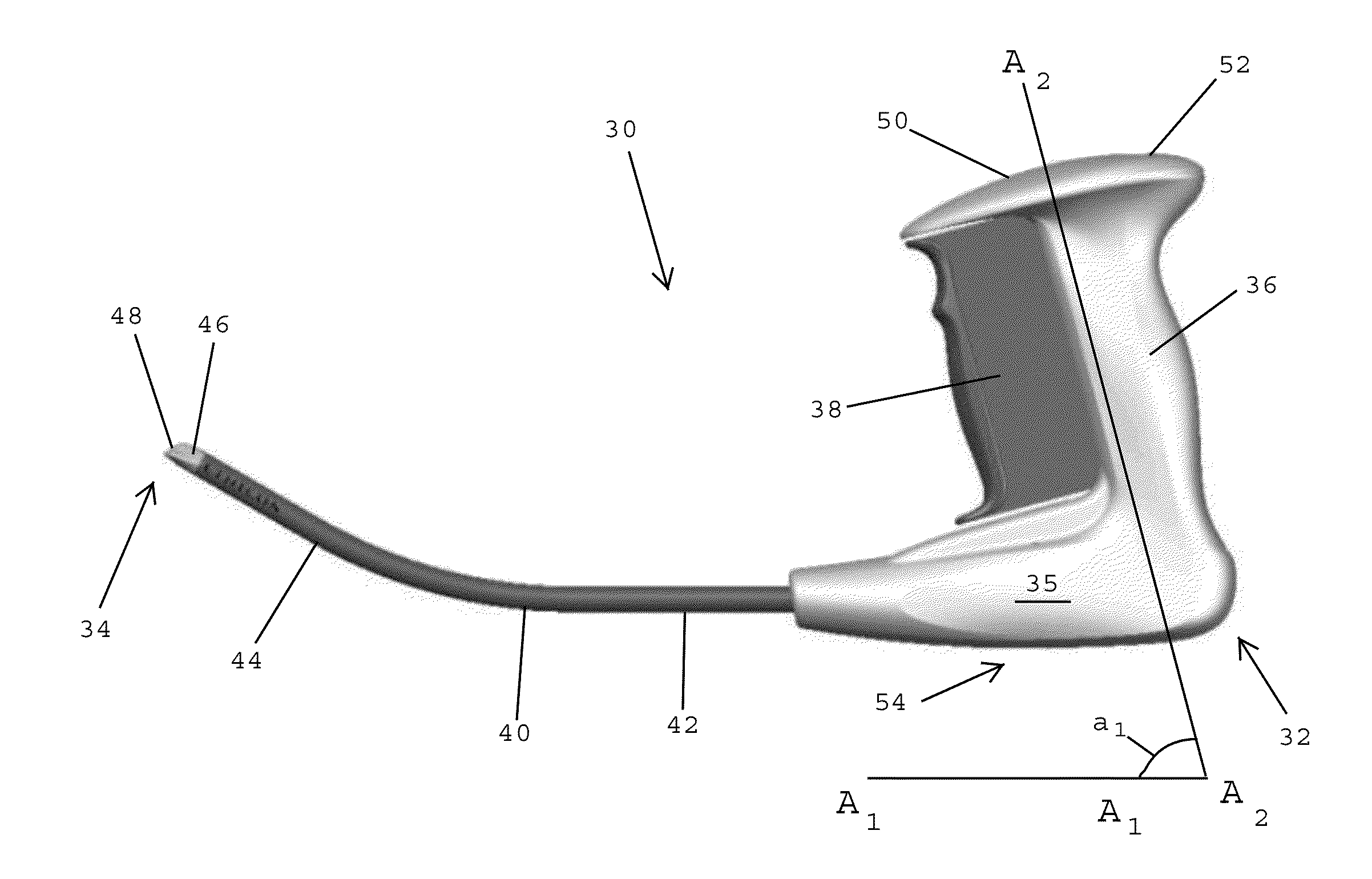
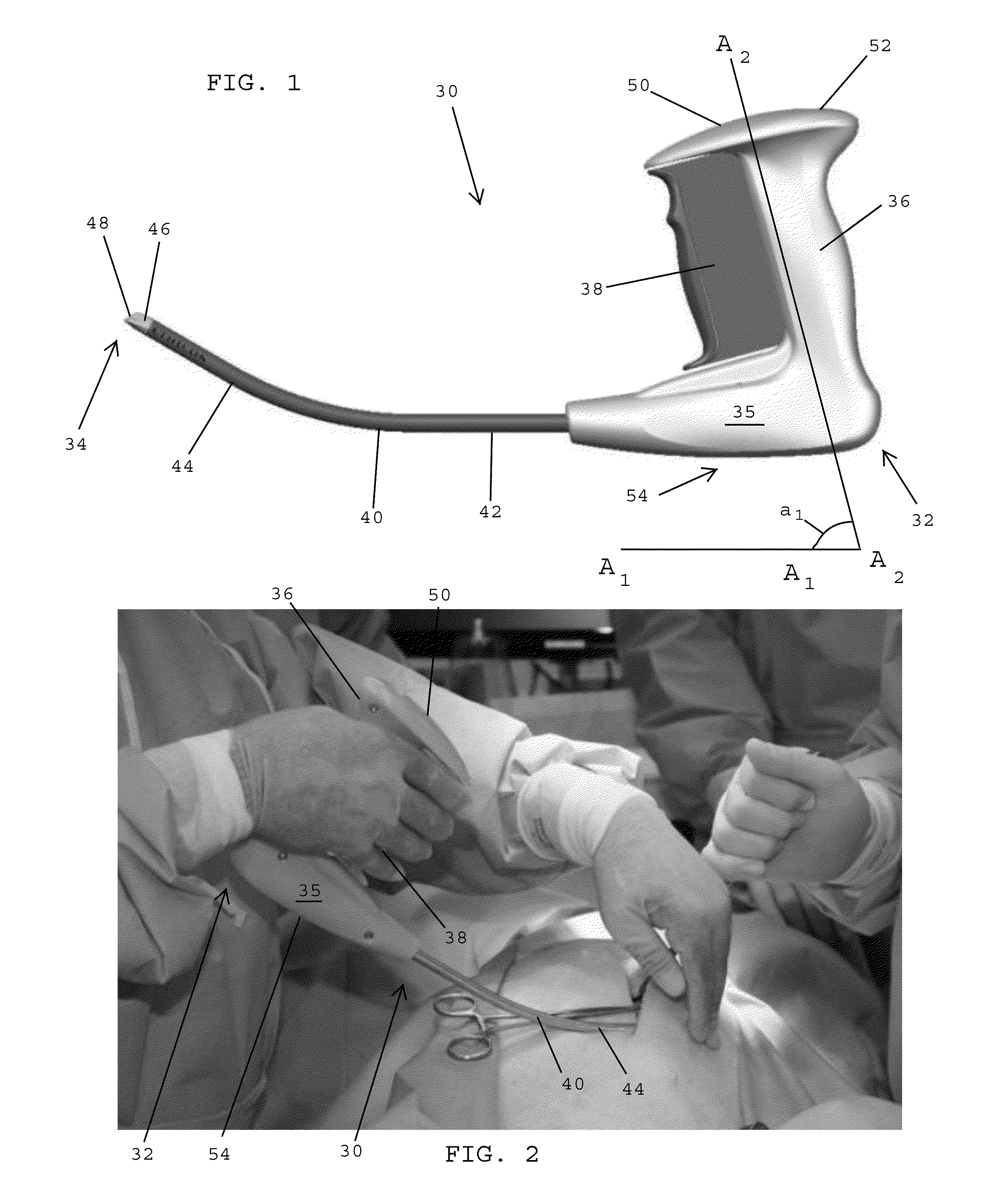
[0102]Referring to FIG. 1, in one embodiment, an applicator instrument 30 for dispensing surgical fasteners has a proximal end 32, a distal end 34, and a longitudinal axis A1-A1 that extends between the proximal and distal ends. The applicator instrument 30 desirably includes a housing 35, a handle 36 extending upwardly from the housing, a trigger 38 mounted on the handle, and an elongated shaft 40 that extends distally from the housing 35. The elongated shaft 40 includes a first section 42 that extends along the longitudinal axis A1-A1 of the applicator instrument, and a second section 44 that is angled or curved relative to the first section 42.

[0103]In one embodiment, a cap 46 is secured to the distal end of the elongated shaft 40. The cap 46 preferably has a distal face 48 that slopes away from a lower distal edge of the cap and toward the proximal end 32 of the applicator instrument 30.

[0104]In one embodiment, the handle 36 includes an upper end 50 containing a counter 52 that ...


PUM


Abstract

An applicator instrument for dispensing surgical fasteners includes a housing, a firing system disposed in the housing, an actuator coupled with the housing for actuating the firing system, an elongated shaft extending from the housing, the elongated shaft having an outer diameter, and a cap secured to the distal end of the elongated shaft, whereby the cap has a lower distal edge that extends laterally beyond the outer diameter of the elongated shaft. The lower distal edge of the cap has a length that is greater than the outer diameter of the elongated shaft. The cap has a distal end face that slopes upwardly and proximally from the lower distal edge, and the cap has a surgical fastener delivery window formed in the distal end face for dispensing surgical fasteners. The delivery window has a lower end that is spaced from the lower distal edge.

Description

CROSS REFERENCE TO RELATED APPLICATIONS[0001]The present application is related to commonly assigned U.S. patent application Ser. No. 13 / 470,022, filed on even date herewith (ETH5635USNP), and U.S. Patent Appln. Publication Nos. US 2010 / 0292715, US 2010 / 0292712, US 2010 / 0292710, US 2010 / 0292713, and US 2011 / 079627, the disclosures of which are hereby incorporated by reference herein.BACKGROUND OF THE INVENTION[0002]1. Field of the Invention[0003]The present invention generally relates to medical devices and surgical procedures for correcting tissue defects, and more specifically relates to applicator instruments having end caps that facilitate the accurate placement of surgical fasteners for the fixation of mesh implants during open repair procedures.[0004]2. Description of the Related Art[0005]Hernia is a condition whereby a small loop of bowel or intestine protrudes through a weak place or defect within the abdominal muscle wall or groin of a patient. This condition commonly occur...

Claims


Application Information

Patent Timeline
IPC IPC(8): A61B17/04
CPCA61B17/0682A61B17/064A61B2017/2946A61B2017/2923A61B2017/003A61B2017/00455A61F2/0063A61F2220/0016A61B2090/08021A61B2090/0807
Inventor STRAEHNZ, JENS-PETERHARMS, VOLKERCARDINALE, MICHAELSOULS, DOUGCOHN, SIMONGABEL, JONATHAN B.
Owner CILAG GMBH INTERNATIONAL
Why Eureka
Try Eureka